background image

33

IQH3B/IQH3BQ 

User Manual

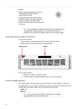
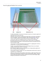
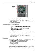
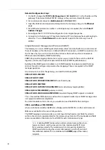
Power Supply and Module Slot Locations

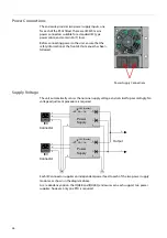
The IQH3B and IQH3BQ 3U Enclosures are designed to accept one or two power supplies with 
independent IEC320 mains connections.

Individually, each PSU module is capable of powering the frame containing any combination 
of IQ-1A/1B modules, subject to the Configuration Rules described on 

page 34

. When two 

units are installed, the operation of the whole frame becomes protected against single-
instance power failures. The manufacturer specifies a maximum of 50 mating cycles.

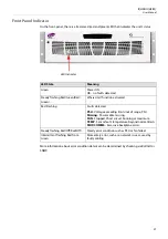
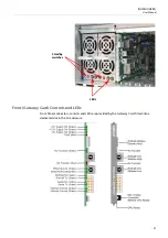
Monitoring circuitry built in to each PSU reports power or PSU fan failures via isolated relay 
contacts on the STATUS connectors on the frame rear panel and the two bi-color LEDs on the 
front of each power supply.

The bi-color LEDs on the PSU front panels are green if the PSU is supplying power to the rack 
and the PSU fans are running, and turn red if either fails.

The LEDs are also red if the mains power to the unit has failed or if the unit is switched to 
standby, provided that the other PSU is functioning.

Within the power supplies, the positive and negative rails are independently regulated and 
have no minimum load current requirements.

The DC outputs of the power supplies have series Schottky diodes that allow direct connection 
of multiple units on one power bus.

Additional components adjust the regulation so that the power supplies will attempt to share 
the load current requirements. The balance of current sharing between supplies is subject to 
variation of the basic regulation of the PSUs. With two PSUs the unit with the higher output 
voltage will contribute more current to the load.
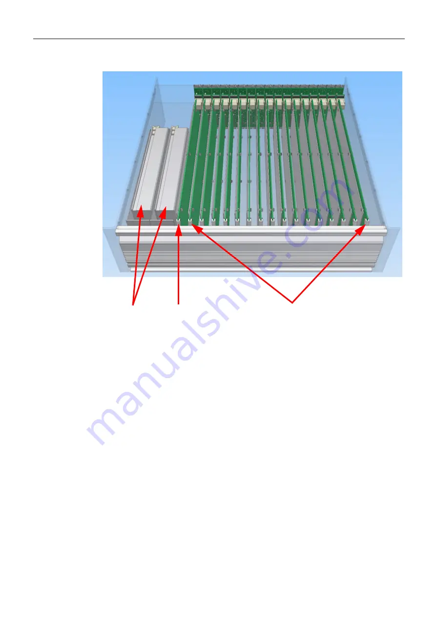
PSUs

Gateway Card

Module Slots 1 to 16

Summary of Contents for grass valley IQH3B Series

Page 1: ...User Manual Issue 3 Revision 1 2019 07 12 IQH3B IQH3BQ IQ 3U MODULAR ENCLOSURE ...

Page 2: ...y hereby grants permission and license to owners of IQH3B IQH3BQ to use their product manuals for their own internal business use Manuals for GrassValley products may not be reproduced or transmitted in any form or by any means electronic or mechanical including photocopying and recording for any purpose unless specifically authorized in writing by Grass Valley A Grass Valley manual may have been ...

Page 3: ...pment connections Identifies an external protective grounding terminal which may be connected to earth ground as a supplement to an internal grounding terminal Indicates that static sensitive components are present which may be damaged by electrostatic discharge Use anti static procedures equipment and surfaces during servicing The presence of this symbol in or on Grass Valley equipment means that...

Page 4: ...al before connecting power Prior to servicing remove jewelry such as rings watches and other metallic objects To avoid fire hazard use only the fuse type and rating specified in the service instructions for this product or on the equipment To avoid explosion do not operate this equipment in an explosive atmosphere Use proper lift points Do not use door latches to lift or move equipment Avoid mecha...

Page 5: ...rame to safely ground unwanted ESD voltages If no wrist strap is available ground yourself by touching the unpainted metal part of the chassis For safety periodically check the resistance value of the antistatic strap which should be between 1 and 10 megohms When temporarily storing a card make sure it is placed in an ESD bag Cards in an earth grounded metal frame or casing do not require any spec...

Page 6: ...e borne de mise à la terre externe qui peut être connectée en tant que borne de mise à la terre supplémentaire Signale la présence de composants sensibles à l électricité statique et qui sont susceptibles d être endommagés par une décharge électrostatique Utilisez des procédures des équipements et des surfaces antistatiques durant les interventions d entretien Le symbole ci contre signifie que l a...

Page 7: ...lisez uniquement un chiffon humide Des tensions dangereuses peuvent exister en plusieurs points dans cet équipement Pour éviter toute blessure ne touchez pas aux connexions ou aux composants exposés lorsque l appareil est sous tension Avant de procéder à toute opération d entretien ou de dépannage enlevez tous vos bijoux notamment vos bagues votre montre et autres objets métalliques Pour éviter to...

Page 8: ...eut se produire lorsque des composants électroniques ne sont pas manipulés de manière adéquate ce qui peut entraîner des défaillances intermittentes ou endommager irrémédiablement un circuit électrique Au moment de remplacer une carte dans un châssis prenez toujours les mesures de protection antistatique appropriées Assurez vous que le châssis est relié électriquement à la terre par le cordon d al...

Page 9: ...lisation Si l écran LCD ou TFT est brisé manipulez les fragments de verre avec précaution au moment de vous en débarrasser veillez à ce que le cristal liquide n entre pas en contact avec la peau ou la bouche En cas de contact avec la peau ou les vêtements laver immédiatement à l eau savonneuse Ne jamais ingérer le liquide La toxicité est extrêmement faible mais la prudence demeure de mise en tout ...

Page 10: ...cycling information Grass Valley believes this environmental information to be correct but cannot guarantee its completeness or accuracy since it is based on data received from sources outside our company All specifications are subject to change without notice If you have questions about Grass Valley environmental and social involvement WEEE RoHS REACH etc please contact us at environment grassval...

Page 11: ...rom its holder using a blunt instrument for leverage such as a screwdriver if necessary In some cases the battery will need to be desoldered from the PCB 4 Dispose of the battery and equipment according to your local environmental laws and guidelines WARNING Be careful not to short circuit the battery by adhering to the appropriate safe handling practices Do not dispose of batteries in a fire as t...

Page 12: ...ating conditions Unused optical outputs should be covered to prevent direct exposure to the laser beam Even though the power of these lasers is low the beam should be treated with caution and common sense because it is intense and concentrated Laser radiation can cause irreversible and permanent damage of eyesight Please read the following guidelines carefully Make sure that a fiber is connected t...

Page 13: ...A PORTS For unconnected signal data ports on the unit fit shielding covers For example fit EMI blanking covers to SFP type ports and fit 75 Ώ RF terminators to BNC type ports COAXIAL CABLES Coaxial cables connections particularly serial digital video connections shall be made with high quality double screened coaxial cables such as Belden 8281 or BBC type PSF1 2M and Belden 1694A for 3Gbps D TYPE ...

Page 14: ...xiv Notices ...

Page 15: ...allation 25 Unpacking the Unit 25 Environment 25 Power Connections 26 Supply Voltage 26 Front Panel Indicator 27 Rear Panel Gateway Card Connections 28 Reference 1 and Reference 2 28 Ethernet 28 PSU Status 29 Remote 29 RollNet 30 Opening and Closing the Front Panel 30 Power Standby Switches 30 Front Gateway Card Controls and LEDs 31 Front Panel Connector 32 Mini 10 way Connector 32 HEX Switches 32...

Page 16: ...8 Java Applet Version 48 Menu Caches Module 48 Start Time 48 Misc Information 1 2 48 Http Server 48 Module Upgrades 49 Power Usage 49 Setup 49 Serial Port Setup 49 Enclosure Type 50 Long File Packets 51 Fan Speed Override 51 Ethernet 52 Unit IP Address Subnet Mask Default Gateway Address 52 TAKE IP Address Changes 53 Link Status 53 IP Routing Setup Status 53 Link Speed 53 MAC Address 53 Hyperion T...

Page 17: ...ket Stats 64 Clear Packet Counts 64 Slots 1 to 16 65 Show Session 65 Gateway Control 66 Control 66 Blind Control 66 Statistics Control 67 SNMP Simple Network Management Protocol 68 Enable SNMP 69 Enable Legacy SNMP 69 Read Community 69 MIB2 sysContact 69 MIB2 sysLocation 69 Write Community 69 MIB2 sysName 69 Read Write Port 69 Resend All Traps 69 Traps 69 Slot Trap Enable 70 SNMP Control 70 Loggin...

Page 18: ...xviii Table of Contents ...

Page 19: ...Single PSU and Ethernet SNMP Compatible RollCall Gateway Card 16 module slots Supplied with plain white unbranded front panel and without mains power cables IQH3B S P BFP Enclosure with Dual Redundant PSU and Ethernet SNMP Compatible RollCall Gateway Card 16 module slots Supplied with plain white unbranded front panel and without mains power cables IQH3BQ S 0 Enclosure with Single PSU and Ethernet...

Page 20: ...ollCall via RollNet RS 232 422 and RollCall over TCP IP control with support for upgradable connectivity to handle future communications standards 2 x analog reference signal distribution for dual standard Bi Level or Tri Level dual video standard SD or HD and reference redundancy applications Hot swappable redundant power supplies with PSU status reporting through GPIs on the Gateway control card...

Page 21: ... in Watts and is the sum of both positive and negative rails On the IQH3B and IQH3BQ power is quoted in Load Units LU which refers to power in Watts taken from the positive rail Feature IQH3A IQH3BQ IQH3B 16 module capacity Hot swappable modules Dual PSUs Dual Cooling Fans Internal reference distribution Integrated control browser Hot swappable Gateway Card Full enclosure monitoring Module Power c...

Page 22: ...22 ...

Page 23: ...anel PC Application Specifications Modules Module Complement 8 double width or 16 single width or combinations of both fitted vertically Module Card Dimensions 100 mm wide 340 mm long Module Rear Panel Dimensions 129 mm high A versions and B versions 40 4 mm double width 20 mm single width wide Power Input Voltage Range 100 240 V 50 60 Hz Input Connector IEC320 Fused 4 A T Standby Switch Behind dr...

Page 24: ...el Analog Reference Return Loss SD bi level 40 dB to 5 5 MHz HD tri level 35 dB to 30 MHz Mechanical Temperature Range 0 to 40 C operating 20 to 85 C storage A temperature and load sensitive cooling fan is fitted Humidity Range 10 to 85 non condensing Case Type 3U rack mounting aluminum case Dimensions W 483 mm 445 mm behind rack location bracket D 490 mm H 135 mm Weight Approximately 8 25 kg with...

Page 25: ...s or damage Report any shortages or damage to Grass Valley immediately Environment Although constructed to meet the normal environmental requirements it is important that there is a free flow of air at the front and rear to dissipate the heat produced during operation Installations should be designed to allow for this When rack mounting the equipment support other than the rack mount ears must be ...

Page 26: ...Voltage The unit automatically senses the nominal supply voltage and sets itself up accordingly No voltage adjustment procedure is required Each IEC connector supplies an independent power feed to each of the two power supply modules as shown in the diagram above As a redundancy option the IQH3B and IQH3BQ enclosures can each support two power supplies however only one PSU is required Power Supply...

Page 27: ...teady flashing Red Green Red Green Where Am I function activated Red Flashing Faults detected PSU Voltage exceeding limits out of range PSU Missing Power cable missing FAN Stopped Short circuit Running at maximum TEMP Sensor fault temperature beyond normal limits MOD COMMS Excessive backplane errors Steady flashing Red Off Red Off Steady error condition such as PSU or fan failed Intermittent flash...

Page 28: ... Status Remote RollNet These BNC connectors allow the unit to be connected to two video reference sources The inputs are terminated in 75 Ohms This RJ45 connector socket allows the unit to be connected to a LAN Two integral yellow LEDs indicate transmit receive activity flashing and the speed 10 Mb OFF 100 Mb ON Note This connector is not intended for direct connection to a telecommunications netw...

Page 29: ...in and switched on Molex Header part number 22 27 2031 Note The NC and NO pins are open circuit when the associated PSU bay is empty The 9 way D type connector on the rear panel allows the unit to be connected to the RollCall 485 network communications system This connector may also be used as a RS 422 or as a RS 232 RollCall communication port Note RS 485 interconnections should be pin to pin and...

Page 30: ...tes the state of the PSU fan The right LED of each pair indicates the state of the PSU output power Green OK Red Fail The BNC connector enables the unit to be connected to the RollCall network communications system The RollCall system should be connected using a 75 Ohm T or Y piece in a similar manner to an Ethernet system Both extremities of the system must be terminated in 75 Ohms Note The coaxi...

Page 31: ...QH3B IQH3BQ User Manual Front Gateway Card Controls and LEDs Front Panel connectors controls and LEDs are provided by the Gateway Card fitted into a dedicated slot in the 3U enclosure Standby switches LEDs ...

Page 32: ...ositions on these switches may be used to set the Unit Address code in Hex Upper switch 1 to f lower switch 0 to f This code will be appear on the 2 digit 7 segment display If a code is already in use the RollCall receive and transmit LEDs will flash alternately at a 1 second rate The two digit RollCall address display has a secondary mode of operation Momentarily press either of the two No Functi...

Page 33: ...power supply The bi color LEDs on the PSU front panels are green if the PSU is supplying power to the rack and the PSU fans are running and turn red if either fails The LEDs are also red if the mains power to the unit has failed or if the unit is switched to standby provided that the other PSU is functioning Within the power supplies the positive and negative rails are independently regulated and ...

Page 34: ...ated in the enclosure Module Power Rating The power rating for each module will be given in the associated operation manual for that module or in the product technical specification available on the Grass Valley Web site Available Power The IQH3B Enclosure has 165 Power Rating units available and the IQH3BQ Enclosure has 100 units available The Power Ratings of each module should be added together...

Page 35: ... Store the blanking plate in a safe place for future use 5 Ensuring correct orientation fit the rear connecting panel supplied with the new module to the rear of the enclosure in the vacant aperture and secure with the fixing screws provided 6 At the front of the enclosure ensuring correct orientation carefully slide in the new module until it fully mates with the rear connector panel 7 Refit the ...

Page 36: ...ed before performing the previous operations However in a live environment this may not be possible and you can remove and install modules without switching the power off Replacement of the Cooling Fan Assembly The cooling fan assembly is located on the rear panel of the 3U enclosure and may be easily replaced without removing the rack from its mounting position or removing any cable connections T...

Page 37: ...tially Instead they should be alternately tightened in small increments to ensure the assembly goes in straight Control Panels A mainframe and the modules that it contains may be controlled by the following methods Control panels connected via the RollCall communications network Computers connected via the RollCall communications network SNMP managers connected via IP Any combination of the above ...

Page 38: ... IQH3B and IQH3BQ enclosures have various interface connections to the RollCall network RollNet 75 Ohm coaxial BNC running at 2 5 Mbps The IQH3B enclosure represents a 2 unit load RollNet RS 485 9 way D type connector running at 2 5 Mbps RS 422 or RS 232 port running at up to 115 2 kbps asynchronous RJ45 Ethernet running at 10 100 Mbps The RS 422 RS 232 and RS 485 interfaces share the same D conne...

Page 39: ...ea network is 4 RS 422 or RS 232 Asynchronous Interface This interface allows a PC running RollCall control software to be connected to the RollCall network without a RollNet interface card The PC is connected via an RS 232 or RS 422 serial port often known as a COM port RS 422 allows longer cable runs and offers better immunity to electrical noise but usually requires an RS 422 to RS 232 converte...

Page 40: ... 2 kbps The RollCall PC software is limited to 57 6 kbps Ethernet Connection This interface allows the 3U enclosure to be connected to a 10 100base T Ethernet network PCs can then connect to the 3U box via TCP IP An Ethernet device connected to a single IQ rack has access to all devices on the RollCall network This interface can be used to connect a PC running the RollCall software A PC can contro...

Page 41: ...figured for RS 232 at 38400 baud Connect the PC COM to the 9 way D type labeled Remote on the rear of the 3U enclosure In the RollCall control window on the PC go to the Ethernet setup page Select Serial Port select the correct COM port and set the Baud rate to 38400 You should now be able to connect to the Gateway IP Crossover Cable You can connect any PC with a 10Base T or 100Base T RJ45 Etherne...

Page 42: ...ules have been created that map controls for each card type and provide other mappings These are required in the SNMP manager operation At a minimum to control the gateway you need the following MIBs SNELL WILCOX SMI MIB SNELL WILCOX TC MIB SNELL WILCOX PRODUCT REG MIB Id for each card type SNELL WILCOX UNIT MIB SNELL WILCOX GATEWAY LOGGING MIB card and gateway logging tables SNELL IQH3A CMD MIB M...

Page 43: ... messages between networks To establish a RollCall bridge The Gateways must be visible to each other via IP Both Gateways must be set to RollNet addresses in the range 0x01 0x0F At least one Gateway must be configured via the Bridge IP Addr control to connect to other s IP address The bridge must be initiated by one Gateway via the Connect or Auto Connect controls ...

Page 44: ...ht be It is recommended that Only Accept This Address is checked at both ends to prevent other Gateways from establishing bridge connections and that Connect Automatically is checked at both ends so the bridge is re connected if it should be disconnected for any reason Gateway 1 Gateway 2 Ethernet Unit IP Address Ethernet Unit IP Address RollCall IP Connect to RollCall IP Connect to ...

Page 45: ...stened Unit Status This area of the template displays abbreviated information about the current status of the unit Line 1 This will normally show the output voltage of the power supplies For example PSU 7 6V 7 8V If a PSU error is detected or a voltage measurement is out of range then the text will toggle to one of the items in the list below Line 2 This will show the Inlet and Outlet temperatures...

Page 46: ...r failure TEMP 28C DISABL Outlet sensor configured as disabled Message Description FAN OK LOW Fan is running OK Low speed mode FAN OK MEDIUM Fan is running OK Medium speed mode FAN OK HIGH Fan is running OK High speed mode FAN OK MAX Fan is running OK Max speed mode IQH3BQ only Note If the frame is configured as a Quiet Enclosure the speed will always be displayed as FAN OK MAX Message Description...

Page 47: ...gured Unit Name This field enables the unit to be given a meaningful name To enter modify the name of the unit type directly into the editable text field and click the Save S button To return to the default name click the Preset P button Serial Number This displays the serial number of the unit ...

Page 48: ...u cache function Start Time This displays the start time for the unit Misc Information 1 2 These information fields may be edited to specify any information desired For example these could be used to add further information on the Gateway Card rack position building group 2 fields are available allowing a maximum of 2 19 characters displayed If these fields have edited values then a corresponding ...

Page 49: ...ages Setup This group enables control of setup functions Net Show This function allows a unit to be hidden from the network system When netshow is active the unit broadcasts its presence Allow Blind Control If the Gateway is to be controlled by Blind Control then Allow Blind Control must be enabled If Blind Control is not used then Allow Blind Control may be disabled giving protection against inco...

Page 50: ...ms should be selected If for some reason one of the power supplies is removed a warning will be displayed indicating which power supply is missing If only one power supply is fitted only the corresponding check box should be selected and the other cleared Enclosure Type The 3U enclosure can be equipped for high power or quiet operation The Enclosure Type radio buttons select which hardware type is...

Page 51: ...ign This control is hidden for newer chassis types A temperature sensor is located at the rear fan For older chassis that had the rear temperature sensor connected through the module i2c bus this control has been added to allow user to override the fan speed The default setting is Medium For this chassis type only the inlet temperature is displayed For all other chassis types an automatic fan spee...

Page 52: ... 255 0 0 Default IP Gateway 0 0 0 0 Note Altering any of these settings while connected to the Gateway via IP may result in the connection being lost If the new values are incorrect it may not be possible to reestablish the connection via IP and so a connection via RollNet or the serial port will have to be made to correct the settings The network administrator should be able to give the correct s...

Page 53: ...rion monitoring feature allowing the viewing of thumbnail image streams sourced from modules within the enclosure to a remote PC Check Client IP When selected only clients from any of the address ranges listed below would be allowed to control this unit Client IP Ranges This item allows the permitted Client IP address to be entered The Gateway can be configured with one or more IP client ranges Ea...

Page 54: ... allows configuration of the IP Bridge function Enable Stats If the Enable Stats box is checked the various packet counters will constantly be updated If Update Packet Stats is disabled these will display a dash Reset Counts When Reset Counts is clicked all the packet counters are reset to zero ...

Page 55: ... This shows the incoming TCP port number of the RollCall IP share connection Port Name This shows the name under which this IP connection appears Port Number This shows which RollCall port on the Gateway this IP connection corresponds to Start Time This shows the time at which this IP connection was started Sent Time This shows if the remote unit on this IP connection has ever sent us a TIME packe...

Page 56: ...he secondary address This ensures that the primary address is used when it is available If the primary connection is not available the secondary connection address will be used Alternate IP Enable Select to allow both the primary and secondary IP addresses to be used When selected Only Accept This Addr s is also automatically selected Only Accept This Addr s This controls whether addresses other t...

Page 57: ...ateway to attempt to connect the IP bridge The Gateway will connect to the IP address and port specified by Bridge IP Addr and Bridge IP Port Disconnect This will cause the Gateway to disconnect the IP bridge If either end of the IP bridge is set to auto connect the bridge then the bridge will be immediately re established Connect Automatically If this is checked the Gateway will automatically try...

Page 58: ...d Logging information will only be sent to the server named in the name window Note matching of the name is case sensitive Any Lo g Server If this item is checked Logging information will be sent to any Logger on the system It is suggested that if there is only one server on the system this option should be chosen Using This displays the name and RollCall address of the current log server If the G...

Page 59: ... is selected the Gateway will accept servers packets via the bridge Last Time Source This shows the address from which the last time packet was received This can be useful in configuring complex networks Only Accept Time from Log Server If this is selected the Gateway will only use time packets from the current log server This can be useful in configuring complex networks ...

Page 60: ...e card is replaced with an incorrect type e g a serial interface the card will appear by its type generic name e g IQCSPI Although the values in this edit box remains the same When this entry is edited the current Installed Unit ID gets copied to the Bound Type ID To enter modify the unit name type a new name in the editable field and click the Save S button To return to the default name click the...

Page 61: ... To return to the default number click Preset P Installed Unit ID This displays the identifier of the module fitted in the slot position Non RollCall This allows a non RollCall card inhabiting slot to be identified See Examples of Slot Use on page 63 for more information Passive units can be given a name indicating to RollMap that a card exists Enable Select this option to indicate that a non Roll...

Page 62: ...y updated in the Power Usage control If a module s ID is not recognized the power usage will indicate If this occurs contact Grass Valley customer service to obtain the correct power usage value Some IQ Modular cards do not appear in the port listing e g SDA31 33 In this case the Non Rollcall Enable check box should be enabled and the type added in the IDNAME field An A type chassis will report po...

Page 63: ...d show Module Status 1 Module Missing on the Logging page The Gateway also logs MSG UNIT LOST for the slot position Module Fitted No Bound Unit If a module is fitted in a slot but no Bound Type is assigned to the slot the generic type name for the module type will be displayed and the slot will appear in the network browser by its slot number and generic type In the absence of other modules the Ga...

Page 64: ...ontroller and from all connected controllers is shown to the right of the controller address The number of blind control packets is shown to the right of the blind controller address If the Update Packet Stats box is unchecked the packet counts will be replaced with dashes Clear Packet Counts When Clear Packet Counts is clicked all packet counters will be reset to zero Note Thepacketsarestillcount...

Page 65: ...ollers usually the first controller Packet counts from this controller and from all connected controllers are displayed to the right Blind This will display the address of the last controller to send the module a blind control packet Packet counts from blind controllers is shown to the right Allow Blind Control If the module is to be controlled by Blind Control RollTrack and some third party remot...

Page 66: ...control packets on all sessions This includes previously closed client session counts This value is cleared by clicking the Clear Packet Count button Show Session Drag the slider to browse different sessions All sessions are indexed from 1 with no gaps in between Click Preset P to return to the default value Disconnect Session When this is clicked the currently displayed session is disconnected Bl...

Page 67: ...istics Control Update Packet Stats If ticked packet counts are updated each second on displayed session and blind controllers Clear Packet Counts Clears and resets connected and blind packet counts resets last blind controller address ...

Page 68: ...ple Network Management Protocol The SNMP page enables configuration of the SNMP agent that operates within the Gateway card Note In order for SNMP to operate there must be a physical Ethernet connection available ...

Page 69: ...rations Default is 161 The SNMP manager should match this value to operate correctly Resend All Traps Resends all current traps notifications for all occupied slots and Gateway card If legacy operation is enabled the associated traps are also sent Traps The Gateway supports up to eight trap destinations Each entry must be unique unless the IP trap address is set to 0 0 0 0 For each trap the user c...

Page 70: ...le control Slot Trap Enable With SNMP enabled these controls allow filtering of trap messages from individual slot positions or even the Gateway Trap sending is only available when control is enabled for the slot See SNMP Control below SNMP Control These check boxes allow filtering of SNMP control to the desired slots gateway only If traps are required on a slot control must also be enabled ...

Page 71: ...er and the current value The only exceptions are Serial Number and Software Version which are always logged and therefore have no enable check box When the check box is enabled that field will be logged to the log server Field Name Field Name Description Valid Field Values Usage Description SN Serial Number Serial Number Format is standard S W serial number consisting of character S followed by ei...

Page 72: ...s subnet or gateway value specified IP Address of unit in Ipv4 dotted decimal notation xxx xxx xxx xxx MODULE_STATUS Module Status OK 1 EXTRA MODULE n EXTRA MODULES 1 MODULE MISSING n MODULES MISSING 1 WRONG TYPE n WRONG TYPES where 2 n 16 Status of module type per slot configuration matching or Modules mismatched missing SESSIONS Control Sessions Number 0 n No of connected CONTROL sessions LAST_M...

Page 73: ...e not user configurable PSU_1_STATE PSU_2_STATE PSU State OK FAIL FAIL Not Fitted Not Used PSU is present and operating correctly PSU presence is detected but not operating PSU is not fitted and theRollCall control for the product has specified that the PSU is fitted PSU is not fitted and theRollCall control for the product has specified that the PSU is NOT fitted RECON_STATE OK Warn Fail 0 RollNe...

Page 74: ...de Use No Link when Ethernet cable unconnected or not init LAN_PORT_n_LAST_ CHANGE Time from start since last Port Change Number DDD HH MM SS Time change when IP interface parameters altered ie IP subnet Uptime in specified format updated every minute NOTE field value is zero buffered 001 08 10 00 is 1 day 8 hours 10 minutes 0 seconds Derived from MIB II ifLastChange LAN_PORT_n_ ERRORS Total numbe...

Page 75: ...CT FROM Note IP address is not zero buffered This column is informational and not to be used for defined error states LAN_PORT_n_STATE Ethernet connection state Active WARN Inactive Does the Ethernet have electrical connectivity UPTIME Uptime in seconds Number DDD HH MM SS Uptime in specified format updated every minute NOTE field value is zero buffered 001 08 10 00 is 1 day 8 hours 10 minutes 0 s...

Page 76: ...Call logging and allows the user to specify which fields will be logged Each log field is shown on a separate line Each has an enable check box a descriptive name the log field header and the current value When the check box is checked that field will be logged to the log server ...

Page 77: ...Not Available FAIL Sensor Fault Disabled Temp is within operating range Temp below normal operating range but not critical Temp above normal operating range but not critical Temp below normal operating range Critical Temp above normal operating range Critical Sensor not detected Sensor malfunction Temperature detection has been manually disabled Each product must specify its own operating ranges a...

Page 78: ...unning OK Medium speed mode Fan is running OK High speed mode Fan is running at maximum speed Fan has ceased running Critical Fan has become short circuit Critical ENCLOSURE Enclosure Name IQH1A IQH3A IQH3B or IQH3BQ Displays the name of the IQ Modular Enclosure MODULE_COMMS State of module comms bus Number of bus errors per 20 seconds Running average of bus errors 0 would indicategoodcomms For IQ...

Page 79: ...nnV nn nnV INFORMATION1 1st Information field Text User definable text INFORMATION2 2nd Information field Text User definable text THUMB_IP_PORT Thumb IP Port value NUMBER Reports the IP Port number used for Hyperion Thumbnail monitoring Ensure enabled if Hyperion monitoring uses the auto discovery feature SNMP_NAME SNMP Name Text Reports the SNMP system name as specified in the MIB2 sysName field...

Page 80: ...ended to log to more than one LogServer It is possible to see more than one LogServer overmultiplenetwork addresses but again this is not recommended POWER_MAX Max Power Available 141W Power for IQH3A 63W IQH1A 165LU IQH3B Load Units Maximum power according to enclosure type POWER_USAGE Power Usage OK nnnW or OK mmmLU e g OK 74W OK 72LU WARN nnnW or WARN mmmLU e g WARN 144W WARN 167LU Current powe...

Page 81: ...dge Status OK Primary Connected OK Secondary Connected FAIL Inactive Disconnected INFO Primary Connected INFO Secondary Connected INFO Inactive Disconnected When enabled changesloggingstate of log field IP_BRIDGE_STATUS to OK or FAIL instead of INFO OK Secondary and INFO Secondary are only displayed if the secondary IP address is enabled and connected Field Name Field Name Description Valid Field ...

Page 82: ...kets that cannot be routed to the indicated destination Dropped Packets This counts packets that cannot be delivered Recons This counts network reconfigurations Network reconfigurations are normal events when units join or leave the network They may also occur occasionally due to electrical interference Constant reconfigurations indicate a physical fault Possible faults include Faulty T piece or c...

Page 83: ...of received Hyperion traffic thumbnails This count cannot be reset Processor Use This reports the processor use The percentage is updated every second This count cannot be reset Enable Net Stats This box must be checked to enable the error counts to be updated If this check box is not enabled all statistics will be displayed as Reset Stats Click this button to reset all statistics to zero ...

Page 84: ...84 ...

Page 85: ...all Control Panel Applet Windows 2000 XP 7 or 10 The Oracle Java Runtime Environment JRE 1 7 or higher The Control Applet has been successfully tested with the following web browsers Internet Explorer Firefox Opening the RollCall Control Panel Applet An overview of how to open the RollCall Control Panel Applet is given below For more information about the RollCall Control Panel Applet refer to the...

Page 86: ...will be displayed 4 In the Warning Security dialog enable Always trust Content from this Publisher then click Run 5 The RollCall Control Panel applet will be downloaded This will take a few moments to display The list of available chassis units and modules is displayed in the network browser area on the left ...

Page 87: ... display a context menu then select Connect to download the RollCall template 7 After a few moments the pages for the selected enclosure are downloaded to the RollCall Control Panel window and the top level Setup page is displayed in the template display area on the right ...

Page 88: ...88 ...

Page 89: ...in a local phone number for the support center nearest you please consult the Contact Us section of Grass Valley s website www grassvalley com An online form for e mail contact is also available from the website Corporate Head Office Grass Valley 3499 Douglas B Floreani St Laurent Quebec H4S 2C6 Canada Telephone 1 514 333 1772 Fax 1 514 333 9828 www grassvalley com ...

Reviews: