104
KAYENNE K-FRAME — Installation & Service Manual
Section 4 — System Cabling
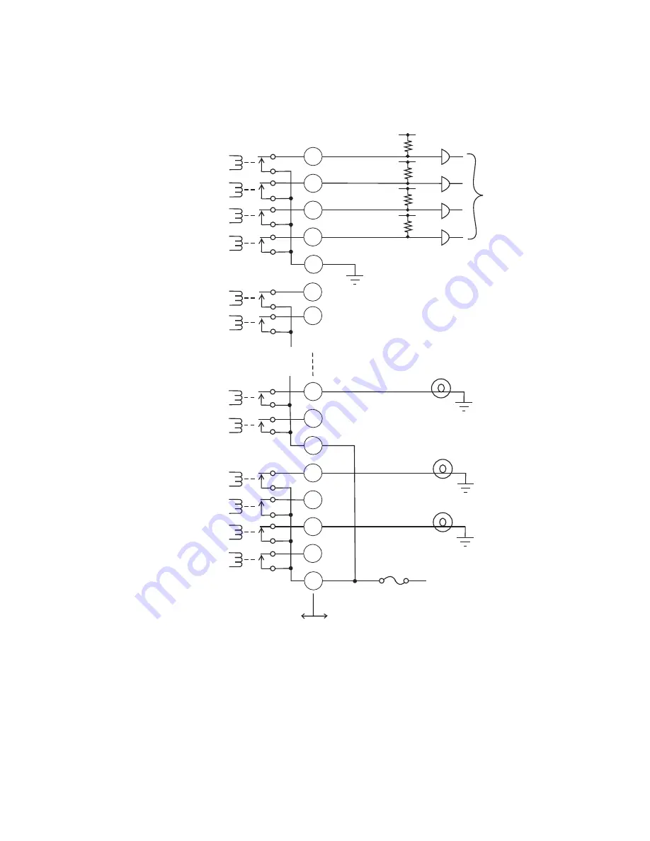
All relays can be used to drive logic or control external circuitry.
Figure 74. Relay Tally and GPI Output Connection Example
Although the diagram shows mechanical relays, the actual outputs are
implemented with solid state relays. The solid state relays are bidirectional;
either polarity voltage can be applied. If the switcher GPI/Relay Tally
outputs are used to drive downstream DC relays, be sure to install diodes
across the relay coils to clamp inductive spikes. Shielded cable is recom-
50-pi
n
Co
nn
ecto
r
Pi
n
N
u
mbe
rs
Tally1A
Tally2A
Tally3A
Tally4A
Tally5B
Tally6B
GPIO
u
t3G
GPIO
u
t4G
GPIO
u
t5H
GPIO
u
t6H
GPIO
u
t7H
GPIO
u
t8H
Video P
r
oce
ss
o
r
F
r
ame
U
s
e
r
Eq
u
ipme
n
t
Commo
n
B
Commo
n
A
Commo
n
H
Logic
12V Lamp
12V Lamp
12V Lamp
+ 12V DC
Commo
n
G
8623266_46_
r
1
21
5
38
22
37
39
23
48
32
47
49
33
17
50
16
Summary of Contents for Grass Valley Kayenne K-Frame
Page 2: ......
Page 30: ...30 KAYENNE K FRAME Installation Service Manual Regulatory Notices ...
Page 42: ...42 KAYENNE K FRAME Installation Service Manual Section 1 Introduction ...
Page 108: ...108 KAYENNE K FRAME Installation Service Manual Section 4 System Cabling ...
Page 208: ...208 KAYENNE K FRAME Installation Service Manual Section 5 Basic Configuration ...
Page 270: ...270 KAYENNE K FRAME Installation Service Manual Maintenance ...


