KAYENNE K-FRAME — Installation & Service Manual
223
Router Interface
Router Interface
Introduction
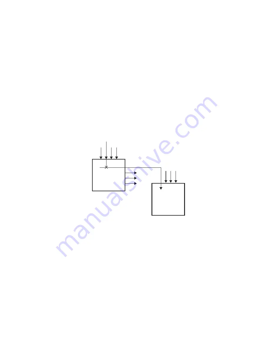
The Kayenne K-Frame system can interface with an external routing
system. A routing system connects a router source (router input) to a router
destination (router output). Changing the router source sends a different
signal to the destination (called a take). A router destination can in turn be
connected to a Kayenne K-Frame input and be configured as a routed
source (called switcher source in this discussion and in the GV Switcher
menus). The router acts as a pre-selector for the switcher source, and so
increases the number of inputs available to a button on a Kayenne K-Frame
system bus.
Figure 151. Router Source, Router Destination, and Routed Switcher Source
An external routing system can be configured into levels, to allow the
switching of multiple signals simultaneously. For example, video signals
can be organized on one level, and key signals on another. By specifying
both levels when giving a router take command, both the video and key
signals of a source will be routed to their destinations.
Note
K-Frame system router Take commands are only applied to all router
levels.The external routing system’s destinations must be configured with all
router levels selected.
Router control panels can also protect router destinations from being
changed by other control panels. A protected router destination cannot be
changed by a different control panel, but may be changed by the panel that
set the protection. Protections help prevent inappropriate router source
changes. The Kayenne K-Frame system can be considered a type of router
control panel, and so the system can protect router destinations. The
Router
Inputs
Router
Outputs
Router
Source
Router
Destination
8804_44
External Routing
System
GV Switcher
Inputs
Routed
GV Switcher
Source
K-Frame System
Summary of Contents for Grass Valley Kayenne K-Frame
Page 2: ......
Page 30: ...30 KAYENNE K FRAME Installation Service Manual Regulatory Notices ...
Page 42: ...42 KAYENNE K FRAME Installation Service Manual Section 1 Introduction ...
Page 108: ...108 KAYENNE K FRAME Installation Service Manual Section 4 System Cabling ...
Page 208: ...208 KAYENNE K FRAME Installation Service Manual Section 5 Basic Configuration ...
Page 270: ...270 KAYENNE K FRAME Installation Service Manual Maintenance ...


