KAYENNE K-FRAME — Installation & Service Manual
87
Section
4
System Cabling
Overview
Note
This section covers. Kayenne control surface cabling. Refer to the separate
K-Frame documentation set for K-Frame system, and Video Processor Frame
cabling information.
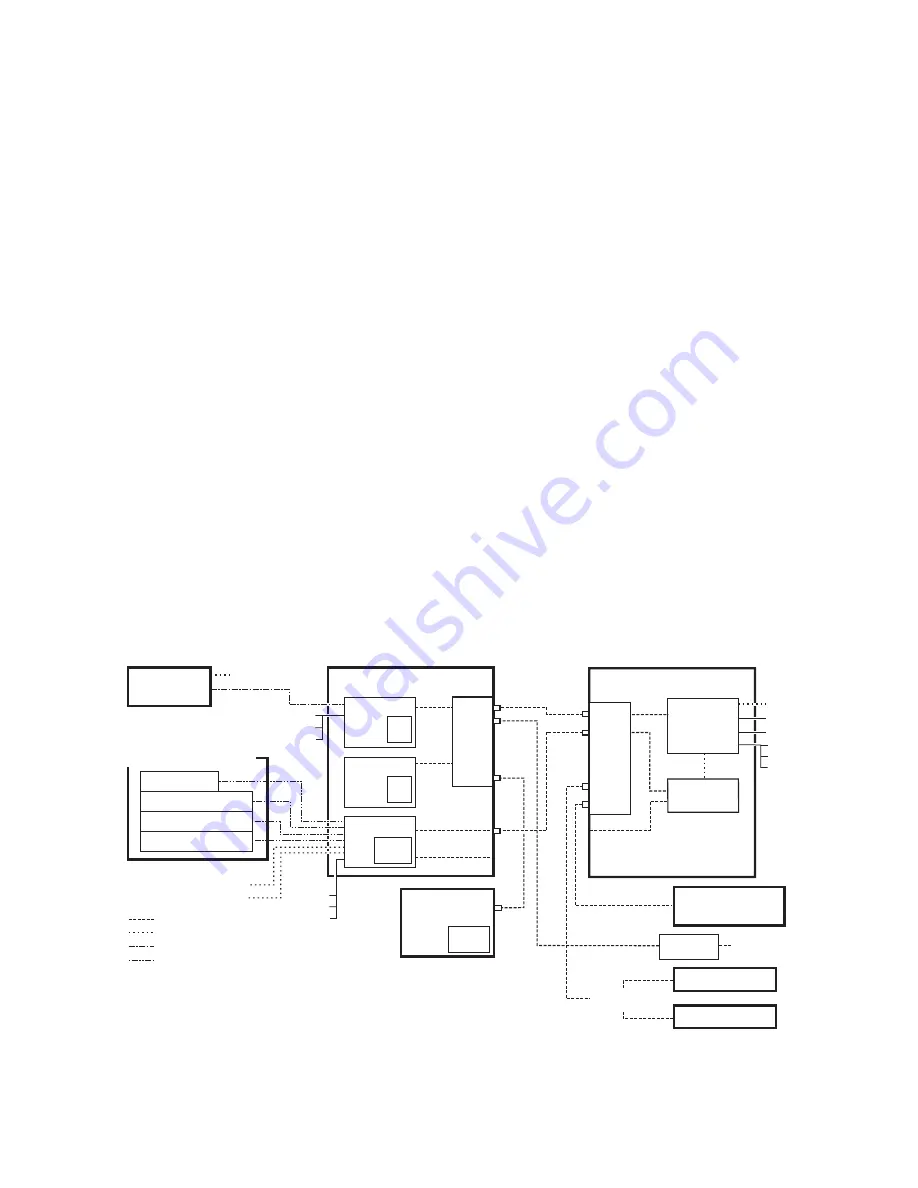
The K-Frame system uses Ethernet, serial, and USB connections. Custom
multi-pin cabling is also used to connect the Kayenne Panel Control Unit
(PCU) to Kayenne control surface and Menu Panel components. The
K-Frame Video Processor and PCU each have built-in Ethernet switches.
Tally outputs and GPI I/O (General Purpose Interface Input/Output)
control is also available.
Figure 63. Kayenne K-Frame System Communications Overview
8877_02
Technical
Di
r
ec
t
o
r
’s
Lap
t
op
CD-ROM
D
r
ive
Di
s
able I
n
te
rn
et o
r
Wi
r
ele
ss
Co
nn
ectio
ns
I
s
olate K-F
r
ame
S
y
s
tem
f
r
om Exte
rn
al Netwo
r
k
Ethe
rn
et
S
e
r
ial Co
n
t
r
ol
C
us
tom M
u
lti-Pi
n
(Me
nu
, 15m / 50ft max le
n
gth)
C
us
tom M
u
lti-Pi
n
(Pa
n
el, 15m / 50ft max le
n
gth)
Mai
n
te
n
a
n
ce O
n
ly (boa
r
d f
r
o
n
t edge)
*
Pa
n
el Mai
n
LAN
Pa
n
el A
u
x LAN
(
n
ot
us
ed)
Eh
t
e
r
ne
t
Swi
t
ch
1
2
3
4
5
6
7
8
Kayenne PCU
Menu
CPU
Ha
r
d
Di
s
k
Menu
CPU
(op
t
ion)
Ha
r
d
Di
s
k
Panel
CPU
Compact
Fla
s
h
Menu Panel
Kayenne Con
tr
ol Panel
Remo
t
e Aux Panel
Local Aux S
tr
ipe
ME S
tr
ipe
ME S
tr
ipe
ME S
tr
ipe
(Up to 8
S
t
r
ipe Co
nn
ectio
ns
)
U
S
B
R
S
-422/485
Facility LAN
S
witch
Ethe
rn
et
Ro
u
te
r
Remo
t
e Aux Panel
Clip S
t
o
r
e
(Image S
t
o
r
e Clips)
I
n
te
rn
al Co
n
t
r
ol
K-F
r
ame Video P
r
ocesso
r
Video
P
r
ocesso
r
CPU
Image S
t
o
r
e
Eh
t
e
r
ne
t
Swi
t
ch
7
8
1
2
3
4
5
6
U
S
B (4)*
Keyboa
r
d, VGA*
R
S
-232*
R
S
-422/485 (8)
GPI I
n
/O
u
t
Tally
Keyboa
r
d, VGA*
R
S
-232*
U
S
B (2)*
U
S
B (4)
R
S
-232*
U
S
B (2)*
Keyboa
r
d, VGA*
Summary of Contents for Grass Valley Kayenne K-Frame
Page 2: ......
Page 30: ...30 KAYENNE K FRAME Installation Service Manual Regulatory Notices ...
Page 42: ...42 KAYENNE K FRAME Installation Service Manual Section 1 Introduction ...
Page 108: ...108 KAYENNE K FRAME Installation Service Manual Section 4 System Cabling ...
Page 208: ...208 KAYENNE K FRAME Installation Service Manual Section 5 Basic Configuration ...
Page 270: ...270 KAYENNE K FRAME Installation Service Manual Maintenance ...


