GUIDE TO INSTALLATION AND OPERATION
18
| XVP-3901-DPI
•
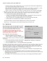
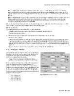
If input 2 and Failover mode are both selected, an error is reported by iControl and the card edge LED turns
red. The second input is always required in this mode.
•
Both input signals must be present – the system cannot switch to input 2 if there is no signal there – and the
absence of either of the signals will be flagged as an error (icon #2 and card-edge LED red)
•
If there is no input 2, the iControl carrier detect icon for input 2 will be red, but no input error will be flagged.
Key / Fill:
when this mode is selected, the card uses input 1 as the main video input, and the second input is
used as background graphics to the output side panels or letterbox. For this mode to function properly:
•
The second input must be the same format as the output.
•
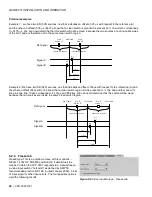
In order for the two signals to be properly phased at the keyer, it is necessary for the second input to be
timed between 414 pixels and 1 line+413 pixels ahead of the output timing.
•
If the second input is lost, the specified background color is used until the input comes back.
•
Input 2 selection in the Input Select area is disabled in the Key/Fill mode.
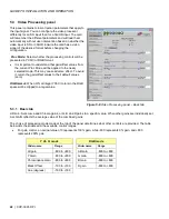
The format and status for the second input is displayed in an icon at the top of the interface.
Key/Fill Output:
Use the pulldown to select whether the Key/Fill output will be SD or HD.
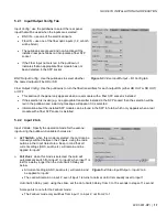
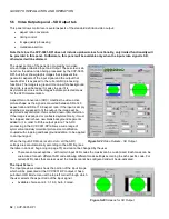
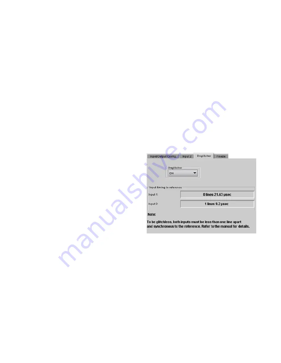
5.2.3 Deglitcher tab
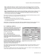
When the Deglitcher is active, the card supports a hot-switch
between two signals (either on the same input, or between
the card’s two inputs) without producing a freeze on the frame
sync, and without producing artifacts on the output.
The deglitcher must be disabled when the input is
asynchronous to the reference. Otherwise, it will create
audio and video glitches at the output.
Mode:
select OFF or ON from the pulldown.
•
Note that the Deglitcher cannot be enabled for
1080p23, 1080p23sF, 1080p25 and 1080p29 sources
For this mode to function correctly, the following requirements
must be met:
•
The two inputs must be synchronized to the reference
•
They must be phased within one line of each other
•
They must be phased to /- ½ line of the HREF of the reference signal
The offset from the VREF can be variable, but a distance of greater than 10 lines could create an artifact in the active
video. If the two signals are more than 1 line apart, we will see a vertical jump at the moment of switching that is
proportional to the number of vertical lines of offset between the two signals. This will last for only one frame. There
may also be problems in the transition when in the AFD automatic or forced mode.
When a reference is present and the deglitcher is active, the card reports the difference in timing between the input
and the reference when the transition occurs.
•
If the reference is missing when the deglitcher is activated, the Input timing to reference box will indicate
“Missing reference” in red, and the reference status icon at the top of the iControl window will turn red and show
the message “Reference missing”.
•
If the deglitcher is OFF, the reference status icon will be grey, and its message will read “Reference absent”
Figure 5-5 Video Input/Output – Deglitcher tab
Summary of Contents for Grass Valley XVP-3901-DPI
Page 4: ...GUIDE TO INSTALLATION AND OPERATION XVP 3901 DPI ...
Page 78: ...GUIDE TO INSTALLATION AND OPERATION 72 XVP 3901 DPI ANNEX 1 XVP 3901 Local User Interface ...
Page 79: ...GUIDE TO INSTALLATION AND OPERATION XVP 3901 DPI 73 ...
Page 80: ...GUIDE TO INSTALLATION AND OPERATION 74 XVP 3901 DPI ...
Page 81: ...GUIDE TO INSTALLATION AND OPERATION XVP 3901 DPI 75 ...


