background image

76

In

st

a

lla

tio

n

DR
AG
O

N

 M

A

C

H

 F

a

m

ily

Re
lease

 04

 02/2
021

7.8

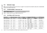
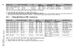
EMC and immunity

EMC interference emission

Standard applications

Railway applications (trackside)

EN 55032

Class A

Fulfilled

Fulfilled

FCC 47 CFR Part 15

Class A

Fulfilled

Fulfilled

EN 61000-6-4

Fulfilled

Fulfilled

EMC interference immunity

Standard applications

a

a. According to EN 61000-6-2.

Railway applications (trackside)

b

b. According to EN 50121-4.

Electrostatic discharge

EN 61000-4-2

Contact discharge

±4 kV

±6 kV

EN 61000-4-2

Air discharge

±8 kV

±8 kV

Electromagnetic field

EN 61000-4-3

80 MHz ... 3000 MHz

max. 10 V/m

max. 20 V/m

Fast transients (burst)

EN 61000-4-4

Supply voltage connection

±2 kV

±2 kV

EN 61000-4-4

Data line

±4 kV

±2 kV

Voltage surges - AC supply connection

EN 61000-4-5

line/ground

±2 kV

±2 kV

EN 61000-4-5

line/line

±1 kV

±1 kV

Voltage surges - data line

EN 61000-4-5

line/ground

±1 kV

±2 kV

Conducted disturbances

EN 61000-4-6

150 kHz ... 80 MHz

10 V

10 V

Immunity

Standard applications

Railway applications (trackside)

IEC 60068-2-6, test Fc

Vibration

5 Hz ... 8.4 Hz with 0.14 in (3.5 mm) amplitude —
8.4 Hz ... 150 Hz with 1 g

IEC 60068-2-27, test Ea 

Shock

15 g at 11 ms

Summary of Contents for Hirschmann DRAGON MACH Series

Page 1: ...Installation DRAGON MACH Family Release 04 02 2021 Technical support https hirschmann support belden com User Manual Installation Modular Industrial Gigabit Ethernet Backbone Switch DRAGON MACH Family ...

Page 2: ...use The performance features described here are binding only if they have been expressly agreed when the contract was made This document was produced by Hirschmann Automation and Control GmbH according to the best of the company s knowledge Hirschmann reserves the right to change the contents of this document without prior notice Hirschmann can give no guarantee in respect of the correctness or ac...

Page 3: ...wer supply unit module 25 1 2 3 Fan module 25 1 3 Power supply 26 1 3 1 Power supply modules 26 1 3 2 Media module D4K 10TP PoE 28 1 4 Signal contact 29 1 5 Ethernet ports 30 1 5 1 10 100 1000 Mbit s twisted pair port 30 1 5 2 100 1000 Mbit s F O port 31 1 5 3 1 2 5 10 Gbit s F O port 31 1 5 4 Support of PoE 31 1 5 5 Out of band management port 32 1 6 Display elements 33 1 6 1 Device state 33 1 6 ...

Page 4: ...e device 52 2 8 Wiring and mounting the signal contact optional 54 2 9 Connecting the supply voltage 56 2 9 1 Power supply modules 56 2 9 2 Media module D4K 10TP PoE 58 2 10 Installing an SFP transceiver optional 59 2 11 Operating the device 59 2 12 Connecting data cables 60 3 Making basic settings 61 4 Monitoring the ambient air temperature 63 5 Maintenance and service 64 6 Disassembly 65 6 1 De ...

Page 5: ...device 73 7 7 2 Power supply unit module 74 7 7 3 Fan module 74 7 7 4 Media modules 75 7 8 EMC and immunity 76 7 9 Network range 77 7 9 1 10 100 1000 Mbit s twisted pair port 77 7 9 2 Fast Ethernet SFP transceiver 77 7 9 3 Bidirectional Fast Ethernet SFP transceiver 78 7 9 4 Gigabit Ethernet SFP transceiver 79 7 9 5 Bidirectional Gigabit Ethernet SFP transceiver 80 7 9 6 2 5 Gigabit Ethernet SFP t...

Page 6: ...6 Installation DRAGON MACH Family Release 04 02 2021 11 Underlying technical standards 88 A Further support 89 ...

Page 7: ...ible injury or death If this symbol is displayed in addition to a safety instruction of the type Danger or Warning it means that there is a danger of electric shock and failure to observe the instructions will inevitably result in injury This symbol indicates the danger of hot surfaces on the device In connection with safety instructions non observance of the instructions will inevitably result in...

Page 8: ...8 Installation DRAGON MACH Family Release 04 02 2021 NOTICE NOTE provides information about procedures that do not involve the risk of injury ...

Page 9: ...ct usage Only use the device for those purposes specified in the catalog and in the technical description Only operate the device with external devices and components that are recommended and permitted by the manufacturer The proper and safe operation of this product depends on proper handling during transport proper storage assembly and installation and conscientious operation and maintenance pro...

Page 10: ...y prevent any mechanical damage to cables wires or conductors caused by external influences or their own weight To prevent damage to device connections connectors and cables follow the instructions for proper installation in accordance with DIN VDE 0100 520 2013 06 sections 522 6 522 7 and 522 13 Qualification requirements for personnel Only allow qualified personnel to work on the device Qualifie...

Page 11: ...s in the fan module fail function and lifetime of a device can be negatively affected or the device may fail completely Use the monitoring functions of the device for individual fans and temperature Depending on your installation conditions it may be possible to continue operating your device after one fan has failed Check the temperature measured by your device In the Command Line Interface use t...

Page 12: ...y without restrictions The electrical wires are voltage free The cables used are permitted for the temperature range of the application case Before you set up other connections connect one of the two ground connections on the front side of the device with the protective conductor When removing connections remove the protective conductor last Exclusively switch on the device when it is installed Re...

Page 13: ...ter of the power supply cable is at least 0 75 mm North America AWG18 on the supply voltage input The cross section of the ground conductor is the same size as or bigger than the cross section of the power supply cables Use a power supply cable which is suitable for the voltage the current and the physical load Media module D4K 10TP PoE The supply voltage input is designed for operation with safet...

Page 14: ... s the EU conformity declaration will be at the disposal of the relevant authorities at the following address Hirschmann Automation and Control GmbH Stuttgarter Str 45 51 72654 Neckartenzlingen Germany www hirschmann com The product can be used in the industrial sector Interference immunity EN 61000 6 2 Emitted interference EN 55032 Safety EN 61010 Warning This is a class A device This device can ...

Page 15: ...te This equipment has been tested and found to comply with the limits for a Class A digital device pursuant to part 15 of the FCC Rules These limits are designed to provide reasonable protection against harmful interference when the equipment is operated in a commercial environment This equipment generates uses and can radiate radio frequency energy and if not installed and used in accordance with...

Page 16: ...description safety instructions a description of the display and the other information that you need to install the device Documentation mentioned in the User Manual Installation that is not supplied with your device as a printout can be found as PDF files for downloading on the Internet at https www doc hirschmann com ...

Page 17: ...Installation DRAGON MACH Family Release 04 02 2021 17 Key The symbols used in this manual have the following meanings Listing Work step Subheading ...

Page 18: ...Ethernet networks according to standard IEEE 802 3 1 1 1 Basic device Figure 1 Basic device DRAGON MACH4000 and DRAGON MACH4500 You can choose from a wide range of variants You have the option to set up your device individually based on different criteria Number of ports Transmission speed Types of connectors Certifications You have numerous options of combining the device characteristics You can ...

Page 19: ...rnet ports or 10 Fast Gigabit Ethernet ports with PoE Seal unused slots with cover panels You obtain the media modules as accessories See Order numbers on page 84 1 1 3 Power supply unit module Figure 3 PSU module Cover panel 1 D4K PSU 300W HV 2 You have the option to operate your basic device non redundantly with 1 PSU module or redundantly with 2 PSU modules Seal unused slots with cover panels Y...

Page 20: ...DRAGON MACH Family Release 04 02 2021 1 1 4 Fan module Figure 4 Fan module D4K AIR The basic device requires 1 fan module to dissipate heat You obtain additional fan modules as accessories See Order numbers on page 84 ...

Page 21: ...Example Media module D4K 12TP RJ45 4 Slot 4 Example Cover panel for media module slot 5 Mounting handle 6 Screw with loss prevention 7 Oblong hole 8 LED display elements for device status 9 Locking lever 10 4 SFP slot for 1 2 5 10 Gbit s connections Fast Ethernet not supported 11 Main Switching Unit MSU 12 Out of band management port 13 Ground connection 11 12 10 9 8 7 6 5 4 1 13 2 3 ...

Page 22: ...e signal contact 4 PSU module Slot 1 Example Cover panel for power supply module slot 5 Screw with loss prevention 6 Supply voltage connection 7 PSU module Slot 2 Example D4K PSU 300W HV 8 LED display element PSU module status 9 Slot for the SD card 10 USB interface 11 Mounting handle 12 Fan module Example D4K AIR 4 3 2 1 5 9 10 7 8 6 11 12 ...

Page 23: ... Example Cover panel for media module slot 5 Mounting handle 6 Screw with loss prevention 7 Oblong hole 8 LED display elements for device status 9 Locking lever 10 8 SFP slot for 1 2 5 10 Gbit s connections Fast Ethernet not supported 11 32 RJ45 socket for 10 100 1000 Mbit s Twisted Pair connections 12 Main Switching Unit MSU 13 Out of band management port 14 Ground connection 12 11 13 10 9 8 7 6 ...

Page 24: ...Supply voltage connection 7 PSU module Slot 2 Example Power supply module D4K PSU 300W HV 8 LED display element PSU module status 9 Slot for the SD card 10 USB interface 11 Mounting handle 12 Fan module D4K 12TP RJ45 Port Port description 1 12 12 RJ45 socket for 10 100 1000 Mbit s Twisted Pair connections D4K 12SFP Port Port description 1 12 12 SFP slot for 100 1000 Mbit s fiber optic connections ...

Page 25: ... 100 1000 Mbit s PoE PD connections D4K PSU 300W HV 1 LED display element PSU module status 2 Safety catch for non heating device cable connector removable 3 Screw with loss prevention 4 Built in non heating device plug C14 plug according to IEC 60320 1 D4K AIR 1 Fan 1 2 Fan 2 3 Fan 3 4 Fan 4 5 Fan 5 6 Screw with loss prevention 7 Mounting handle 3 1 2 4 5 9 6 7 8 10 11 3 1 4 2 1 2 4 3 5 6 7 ...

Page 26: ...wer supply 1 3 1 Power supply modules You have the following options to supply your device with voltage Figure 5 Power supply PSU modules rear side of device Non redundantly via 1 PSU module with built in non heating device plug C14 plug according to IEC 60320 1 ...

Page 27: ...allation DRAGON MACH Family Release 04 02 2021 27 Figure 6 Power supply PSU modules rear side of device Redundantly via 2 PSU modules with built in non heating device plug C14 plug according to IEC 60320 1 ...

Page 28: ...ply of terminal devices with PoE voltage via twisted pair cable To supply the module with PoE voltage you need an external power supply unit Details about the power supply of the media module can be found in chapter Supply voltage on page 70 Figure 7 Power supply Terminal block on the media module 1 2 3 4 5 6 7 8 10 9 54 V DC 8 4 A ...

Page 29: ...y closed contact 1 see figure 8 The signal contact allows you to control external devices or monitor device functions In the configuration you specify how the device uses the signal contact You will find detailed information on possible applications and the configuration of the signal contact in the software user documentation You will find the software user documentation as PDF files on the Inter...

Page 30: ...ng to the IEEE 802 3 10BASE T 100BASE TX 1000BASE T standard This port supports Autonegotiation Autopolarity Autocrossing if autonegotiation is activated 1000 Mbit s full duplex 100 Mbit s half duplex mode 100 Mbit s full duplex mode 10 Mbit s half duplex mode 10 Mbit s full duplex mode Delivery state Autonegotiation activated Pin assignments RJ45 Pin 10 100 Mbit s 1000 Mbit s MDI mode 1 TX BI_DA ...

Page 31: ...ate 1 2 5 10 Gbit s full duplex when using a Gigabit Ethernet SFP transceiver 1 5 4 Support of PoE Prerequisites for the support of PoE PoE At least 1 media module with PoE PoE functionality D4K 10TP PoE is mounted in the basic device Note PoE PoE is exclusively available with PoE capable media modules The DRAGON basic device has no PoE capable ports Note Connect only PoE powered devices whose dat...

Page 32: ...port supports 100 Mbit s half duplex 100 Mbit s full duplex The port allows you to manage the device and upload configurations via the following protocols SNMP SSH Telnet FTP SCP HTTP HTTPS For more information see the Command Line Interface reference manual You find the manual available as download on the Internet at www doc hirschmann com RJ45 Pin 10 100 Mbit s 1000 Mbit s PoEa a Exclusively for...

Page 33: ... Device is starting and or is not ready for operation green lights up Device is ready for operation Characteristics can be configured red lights up Device is ready for operation Device has detected at least one error in the monitoring results flashes 1 time a period The boot parameters used when the device has been started differ from the boot parameters saved Start the device again flashes 4 time...

Page 34: ...hts up Supply voltage 1 and 2 is on P1 Supply voltage none At least one of the following cases applies Power supply module is not connected to slot P1 There is no external supply voltage or it is too low No connection between PSU module and basic device green lights up The following applies Power supply module is connected to slot P1 Valid supply voltage connected Boot procedure started P2 Supply ...

Page 35: ...been started differ from the boot parameters saved Start the device again flashes 4 times a period Device has detected a multiple IP address ACA Storage medium ACA22 ACA31 none ACA storage medium not connected green lights up ACA storage medium connected flashes 3 times a period Device writes to reads from the storage medium yellow lights up ACA storage medium inoperative RM Ring Manager none No r...

Page 36: ...ow No connection between PSU module and basic device green lights up The following applies Power supply module is connected to slot P1 Valid supply voltage connected Boot procedure started P2 Supply voltage none At least one of the following cases applies Power supply module is not connected to slot P2 There is no external supply voltage or it is too low No connection between PSU module and basic ...

Page 37: ...o connection between PSU module and basic device PSU module not operational green lights up At least one of the following cases applies PSU module is plugged in Valid supply voltage connected red flashes 1 time a period At least one of the following cases applies Supply voltage is too low Supply voltage too high PSU module fan failed Overheating warning green red flashing alternately Overload curr...

Page 38: ...e display elements on the device front side of the device Figure 14 Port status location of the display elements on the device front side of the device Note In the present hardware version the lower port LEDs of the RJ45 ports are without function N A The port status of all ports is displayed via the upper port LEDs 1 2 3 4 L D L D 32 31 32 L D 31 N A ...

Page 39: ...ed off yellow lights up Device detects a non supported SFP transceiver or a non supported data rate flashing alternately Device is transmitting and or receiving data flashes 1 time a period Device detects at least one unauthorized MAC address Port Security Violation and sends a trap flashes 3 times a period The device deactivates the relevant port auto deactivation LED Display Color Activity Meani...

Page 40: ...edia module is inoperative green lights up Voltage supply to the media module is on L D Link state data traffic none Device detects an invalid or missing link green lights up Device detects a valid link flashes 1 time a period Port is switched to stand by flashes 3 times a period Port is switched off yellow flashing Device is transmitting and or receiving data flashes 1 time a period Device detect...

Page 41: ... invalid or missing link green lights up Device detects a valid link flashes 1 time a period Port is switched to stand by flashes 3 times a period Port is switched off yellow lights up Device detects a non supported SFP transceiver or a non supported data rate flashing Device is transmitting and or receiving data flashes 1 time a period Device detects at least one unauthorized MAC address Port Sec...

Page 42: ...ing link green lights up Device detects a valid link flashes 1 time a period Port is switched to stand by flashes 3 times a period Port is switched off yellow flashing Device is transmitting and or receiving data flashes 1 time a period Device detects at least one unauthorized MAC address Port Security Violation flashes 3 times a period The device deactivates the relevant port auto deactivation Po...

Page 43: ...00 terminal or PC with corresponding terminal emulation This enables you to set up a connection to the Command Line Interface CLI and to the system monitor The socket housing is electrically connected to the front panel of the device The V 24 interface is electrically insulated from the supply voltage VT100 terminal settings Speed 9600 Baud Data 8 bit Stopbit 1 bit Handshake off Parity none Figure...

Page 44: ... data and diagnostic information and for loading the software See Accessories on page 85 On the front and rear side of the device there are LEDs that inform you about the status of the interface The USB interface has the following properties Supplies current of max 500 mA Voltage not potential separated Connectors type A Supports the USB master mode Supports USB 2 0 Figure Pin Function 1 VCC VBus ...

Page 45: ...nterface Location on the device rear side of the device The SD card interface allows you to connect the AutoConfiguration Adapter ACA31 storage medium This is used for saving loading the configuration data and diagnostic information and for loading the software On the front and rear side of the device there are LEDs that inform you about the status of the interface ...

Page 46: ... SD card optional Installing a cover panel optional Installing a power supply module Installing a media module optional Mounting the fan module Installing and grounding the device Wiring and mounting the signal contact optional Connecting the supply voltage Installing an SFP transceiver optional Operating the device Connecting data cables 2 1 Checking the package contents Check whether the package...

Page 47: ...ssories on page 85 Figure 22 Inserting an SD card Location on the device rear side of the device Proceed as follows Deactivate the write protection on the SD card by pushing the write protect lock towards the middle of the card Unscrew the top right side screw of the SD card slot cover Slide the cover clockwise using the unscrewed screw The SD card slot is now accessible ...

Page 48: ...crewed screw Secure the SD card by screwing the cover 2 3 Installing a cover panel optional Prerequisite To comply with the EMC requirements seal unused open slots with a cover panel you obtain cover panels as an accessory See Order numbers on page 84 Proceed as follows Place the matching cover panel over the power supply module slot or media module slot of the device Fasten the cover panel to the...

Page 49: ...t swappable Figure 24 Mounting a PSU module Installation rear side of the device Proceed as follows Remove the cover panel if mounted from the power supply module slot on the device 1 Insert the power supply module straight into the slot 2 Fasten the power supply module to the device by tightening the 2 screws 3 You find the prescribed tightening torque in chapter General data on page 69 2 1 3 ...

Page 50: ...slot on the basic device Open the locking mechanism of the media module by pressing the locking levers outwards 1 Insert the media module straight into the media module slot 2 Lock the media module in place by pressing the locking levers inwards 3 Fasten the media module with the screws in the front panel of the basic device You find the prescribed tightening torque in chapter General data on page...

Page 51: ...moving the fan module during active operation the individual fans continue to spin for a few seconds Do not touch rotating fan blades Do not insert objects into rotating fan blades Failure to follow these instructions can result in injury or equipment damage NOTICE OVERHEATING OF THE DEVICE The device may overheat if the fan module fails or is removed Switch off the device or replace the fan modul...

Page 52: ...ht into the slot Fasten the fan module to the device by tightening the 2 screws You find the prescribed tightening torque in chapter General data on page 69 2 7 Installing and grounding the device Mounting in a switch cabinet WARNING ELECTRIC SHOCK Exclusively install this device in a switch cabinet or in a restricted access location according to EN 62368 1 to which maintenance staff have exclusiv...

Page 53: ...binet to prevent the device from overheating Measure the depth of the 19 cabinet so that all the lines to be connected can be fed in easily Proceed as follows Assemble the sliding or mounting rails in the 19 switch cabinet as specified by the manufacturer Position the device on the rails in the switch cabinet Fasten the device in the switch cabinet by screwing it in with the mounting brackets Grou...

Page 54: ...gure 29 Signal contact 3 pin terminal block with screw lock position on the device rear side of the device WARNING ELECTRIC SHOCK Start connecting electrical wires only if all safety requirements listed in chapter General safety instructions are fulfilled Failure to follow these instructions can result in death serious injury or equipment damage WARNING ELECTRIC SHOCK Never insert sharp objects sm...

Page 55: ...block connections Fasten the wires in the terminal block by tightening the terminal screws Mount the terminal block on the device using screws You find the prescribed tightening torque in chapter General data on page 69 Signal contact 1 NC Normally closed contact 2 CO Changeover contact 3 NO Normally open contact 1 2 3 FAULT ...

Page 56: ...RIC SHOCK Start connecting electrical wires only if all safety requirements listed in chapter General safety instructions are fulfilled Failure to follow these instructions can result in death serious injury or equipment damage WARNING ELECTRIC SHOCK Never insert pointed objects narrow screwdrivers wires etc into the device or into the connection terminals for electric conductors Do not touch the ...

Page 57: ...IEC 60320 1 into the power supply connection built in C14 plug of the PSU module Secure the coupling against falling out by sliding the safety catch of the built in non heating appliance plug over the coupling Type of the voltages that can be connected Specification of the supply voltage Pin assignment AC voltage Rated voltage range 110 V AC 240 V AC 50 Hz 60 Hz L N Outer conductor Neutral conduct...

Page 58: ... Fasten the wires in the terminal block by tightening the terminal screws Mount the terminal block on the device using screws By connecting the PoE supply voltage you put the PoE functionality into operation Note Exclusively pull and plug the terminal block of the PoE power supply on the D4K 10TP PoE media module in a voltage free state The media module D4K 10TP PoE is not hot pluggable Note The m...

Page 59: ...essories on page 85 Figure 32 Installing SFP transceivers Installation sequence Proceed as follows Take the SFP transceiver out of the transport packaging 1 Remove the protection cap from the SFP transceiver 2 Push the SFP transceiver with the lock closed into the slot until it latches in 3 2 11 Operating the device Proceed as follows Enable the supply voltage 3 ...

Page 60: ...the power supply cables and the data cables Ideally install the cables in separate cable channels Verify that power supply cables and data cables do not run parallel over longer distances To reduce inductive coupling verify that the power supply cables and data cables cross at a 90 angle Use shielded data cables for gigabit transmission via copper cables for example SF UTP cables according to ISO ...

Page 61: ...iView http www hirschmann com en QR INET HiView Industrial HiVision http www hirschmann com en QR INET Industrial HiVision Default settings IP address The device looks for the IP address using DHCP Password for management Login user password public read only Login admin password private read and write Parameters that can be set via the management are set to pre defined values in accordance with th...

Page 62: ...s you to type in a new password Type in your new password To help increase security choose a password that contains at least 8 characters which includes upper case characters lower case characters numerical digits and special characters When you log on to the device with the Command Line Interface then the device prompts you to confirm your new password Log on to the device again with your new pas...

Page 63: ...ambient air temperature exclusively See Climatic conditions during operation on page 72 The ambient air temperature is the temperature of the air at a distance of 2 in 5 cm from the device It depends on the installation conditions of the device for example the distance from other devices or other objects and the output of neighboring devices ...

Page 64: ... fuses are triggered only in the case of a detected error in the device In case of damage or malfunction of the device turn off the supply voltage and return the device to the plant for inspection Hirschmann is continually working on improving and developing their software Check regularly whether there is an updated version of the software that provides you with additional benefits You find inform...

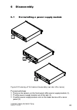
Page 65: ... supply module Figure 33 Removing a PSU module Disassembly rear side of the device Proceed as follows Remove the screws on the front panel of the power supply module 1 Pull the power supply module out of the slot 2 Seal the power supply module slot on the basic device with a cover panel 3 2 1 3 ...

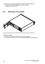
Page 66: ...e You find the prescribed tightening torque in chapter General data on page 69 6 2 Removing a fan module Figure 34 Removing a fan module Disassembly rear side of the device Proceed as follows Unscrew the 2 screws of the fan module on the device Pull the fan module out of the slot using the foldable mounting handle ...

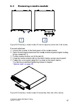
Page 67: ...media module Open the locking mechanism of the media module by pressing the locking levers outwards 1 Pull the media module out of the slot 2 Close the media module slot on the basic device using a cover panel Fasten the cover panel using the 2 screws on the basic device You find the prescribed tightening torque in chapter General data on page 69 Figure 36 Removing a media module Disassembly front...

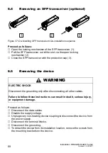
Page 68: ...ection cap 3 6 5 Removing the device Proceed as follows Disconnect the data cables Disable the supply voltage Unplug every non heating device coupling to disconnect the device from the power supply Disconnect the terminal blocks Disconnect the grounding To detach the device from its installation location remove the screws from the mounting brackets on the device WARNING ELECTRIC SHOCK Disconnect t...

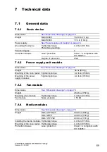
Page 69: ...of protection IP20 Dimensions See Dimension drawings on page 73 Weight 30 oz 850 g Mounting of the cover panel Tightening torque 4 4 lb in 0 5 Nm Mounting of the power supply modules Tightening torque 4 4 lb in 0 5 Nm Dimensions See Dimension drawings on page 73 Weight 26 46 oz 750 g Mounting a fan module Tightening torque 4 4 lb in 0 5 Nm Fan module Noise emission 50 dB Dimensions See Dimension d...

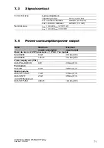
Page 70: ...tage input Nominal rating 6 3 A Characteristic slow blow Peak inrush current 20 A 6 ms Current integral I t 1 8 A s Crest factor 4 Connection for protective ground See Grounding the device on page 53 Rated voltage 54 V DC Voltage range incl maximum tolerances 52 V DC 57 V DC Connection type 2 pin terminal block Tightening torque 4 4 lb in 0 5 Nm min conductor diameter AWG14 1 5 mm max conductor di...

Page 71: ... 1 3 mm Nominal value Imax 2 A at Umax 230 V AC Imax 2 A at Umax 30 V DC Name Maximum power consumption Maximum power output Basic device incl SFP transceivers 1 PSU Fan module MACH4000 80 W 273 Btu IT h MACH4500 120 W 410 Btu IT h Power supply unit PSU D4K PSU 300W HV 6 W 21 Btu IT h Fan module D4K AIR 20 W 68 Btu IT h Media modules D4K 12TP RJ45 15 W 51 Btu IT h D4K 12SFP incl SFP transceiver 25...

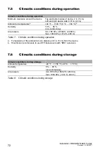
Page 72: ...emperature of the ambient air at a distance of 2 in 5 cm from the device 32 F 140 F 0 C 60 C b b Hirschmann recommends to use SFP transceivers with EEC extension Humidity 10 95 non condensing Air pressure min 795 hPa 6562 ft 2000 m max 1060 hPa 1312 ft 400 m Table 7 Climatic conditions during operation Climatic conditions during storage Ambient temperature 40 F 158 F 40 C 70 C Humidity 5 95 non co...

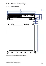
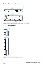
Page 73: ...DRAGON MACH Family Release 04 02 2021 73 7 7 Dimension drawings 7 7 1 Basic device Figure 38 Dimension drawings basic device 10 0 39 3 0 12 R 3 5 R 0 1 4 88 8 3 5 76 2 3 482 18 98 465 25 39 445 17 52 440 17 32 mm in ...

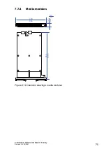
Page 74: ...y Release 04 02 2021 7 7 2 Power supply unit module Figure 39 Dimension drawings power supply unit module 7 7 3 Fan module Figure 40 Dimension drawings fan module 42 1 65 277 10 91 250 9 84 80 3 15 mm in mm in 55 2 17 85 3 35 410 16 14 ...

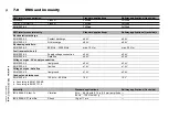
Page 75: ...Installation DRAGON MACH Family Release 04 02 2021 75 7 7 4 Media modules Figure 41 Dimension drawings media modules 22 5 0 9 334 13 15 mm in 220 8 66 ...

Page 76: ...charge 4 kV 6 kV EN 61000 4 2 Air discharge 8 kV 8 kV Electromagnetic field EN 61000 4 3 80 MHz 3000 MHz max 10 V m max 20 V m Fast transients burst EN 61000 4 4 Supply voltage connection 2 kV 2 kV EN 61000 4 4 Data line 4 kV 2 kV Voltage surges AC supply connection EN 61000 4 5 line ground 2 kV 2 kV EN 61000 4 5 line line 1 kV 1 kV Voltage surges data line EN 61000 4 5 line ground 1 kV 2 kV Condu...

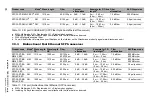
Page 77: ...BLP Dispersion M FAST SFP MM LC MM 1310 nm 50 125 µm 0 dB 8 dB 0 mi 3 11 mi 0 km 5 km 1 0 dB km 800 MHz km M FAST SFP MM LC MM 1310 nm 62 5 125 µm 0 dB 11 dB 0 mi 2 49 mi 0 km 4 km 1 0 dB km 500 MHz km M FAST SFP SM LC SM 1310 nm 9 125 µm 0 dB 13 dB 0 mi 15 53 mi 0 km 25 km 0 4 dB km 3 5 ps nm km M FAST SFP SM LC SM 1310 nm 9 125 µm 10 dB 29 dB 15 53 mi 40 39 mi 25 km 65 km 0 4 dB km 3 5 ps nm km ...

Page 78: ...ing 3 dB system reserve when compliance with the fiber data is observed Fiber attenuation BLP Dispersion SFP FAST BA MM LC EEC MM 1310 nm 1550 nm 50 125 µm 62 5 125 µm 0 dB 16 dB 0 mi 1 24 mi 0 km 2 km 1 0 dB km 800 MHz km 500 MHz km SFP FAST BB MM LC EEC MM 1550 nm 1310 nm 50 125 µm 62 5 125 µm 0 dB 16 dB 0 mi 1 24 mi 0 km 2 km 1 0 dB km 800 MHz km 500 MHz km SFP FAST BA SM LC EEC SM 1310 nm 1550...

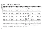
Page 79: ... SFP LX LC MM 1310 nmd 62 5 125 µm 0 dB 10 5 dB 0 mi 0 34 mi 0 km 0 55 km 1 0 dB km 500 MHz km M SFP LX LC SM 1310 nm 9 125 µm 0 dB 10 5 dB 0 mi 12 43 mi 0 km 20 km e 0 4 dB km 3 5 ps nm km M SFP LX LC SM 1310 nm 9 125 µm 5 dB 20 dB 8 70 mi 26 10 mi 14 km 42 km 0 4 dB km 3 5 ps nm km M SFP LH LC LH 1550 nm 9 125 µm 5 dB 22 dB 14 29 mi 49 71 mi 23 km 80 km 0 25 dB km 19 ps nm km M SFP LH LC LH 1550...

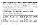
Page 80: ...d g With F O adapter compliant with IEEE 802 3 2002 Clause 38 single mode fiber offset launch mode conditioning patch cord h Including 2 5 dB system reserve when compliance with the fiber data is observed Product code Modea Wavelength TX Wave length RX Fiber System attenuation Example for F O line lengthb Fiber attenuation BLP Dispersion M SFP BIDI Type A LX LC EEC SM 1310 nm 1550 nm 9 125 µm 0 dB...

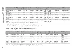
Page 81: ...ding 3 dB system reserve when compliance with the fiber data is observed Product code Modea Wave length Fiber System attenuation Example for F O line lengthb Fiber attenuation BLP Dispersion M SFP 2 5 MM LC EEC MM 850 nm 50 125 µm 0 dB 4 dB 0 34 mi 0 55 km 3 5 dB km 2000 MHz km OM3 M SFP 2 5 MM LC EEC MM 850 nm 50 125 µm 0 dB 4 dB 0 25 mi 0 4 km 3 5 dB km 500 MHz km OM2 M SFP 2 5 MM LC EEC MM 850 ...

Page 82: ...ersion M SFP 10 SR LC EEC MM 850 nm 50 125 µm 0 dB 8 1 dB 0 041 mi 0 066 km 3 dB km 400 MHz km M SFP 10 SR LC EEC MM 850 nm 50 125 µm 0 dB 8 1 dB 0 051 mi 0 082 km 3 dB km 500 MHz km OM2 M SFP 10 SR LC EEC MM 850 nm 50 125 µm 0 dB 8 1 dB 0 186 mi 0 3 km 3 dB km 2000 MHz km OM3 M SFP 10 SR LC EEC MM 850 nm 50 125 µm 0 dB 8 1 dB 0 25 mi 0 4 km 3 dB km 4700 MHz km OM4 M SFP 10 SR LC EEC MM 850 nm 62 ...

Page 83: ...k for signal contact 1 Fan module D4K AIR 4 Cover panel for media module slot 1 Cover panel for power supply module slot Amount Article 1 Media module 1 Safety and general information sheet 1 2 pin terminal block for the PoE supply voltage exclusively with media module D4K 10TP PoE Amount Article 1 Power supply module 1 Safety and general information sheet Amount Article 1 Fan module D4K AIR 1 Saf...

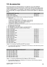
Page 84: ...CH4500 80G 8X L2A 942 153 001 DRAGON MACH4500 80G 8X L3A UR 942 153 002 DRAGON MACH4500 80G 8X L3A MR 942 153 003 Fan module D4K AIR 942 157 001 Power supply unit PSU D4K PSU 300W HV 942 156 001 Media module D4K 12TP RJ45 942 155 001 Media module D4K 10TP PoE 942 294 001 Media module D4K 12SFP 942 155 501 Cover panel for media module slot 942 222 001 Cover panel for power supply unit slot 942 222 ...

Page 85: ... Not applicable for combo ports Not applicable for ports which support only Gigabit Ethernet It is currently not possible to set autocrossing manually M FAST SFP MM LC 943 865 001 M FAST SFP MM LC EEC 943 945 001 M FAST SFP SM LC 943 866 001 M FAST SFP SM LC EEC 943 946 001 M FAST SFP SM LC 943 867 001 M FAST SFP SM LC EEC 943 947 001 M FAST SFP LH LC 943 868 001 M FAST SFP LH LC EEC 943 948 001 S...

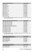
Page 86: ...X LC EEC 943 974 002 M SFP BIDI Type A LH LC EEC 943 975 001 M SFP BIDI Type B LH LC EEC 943 975 002 M SFP BIDI Bundle LX LC EEC Type A B 943 974 101 M SFP BIDI Bundle LH LC EEC Type A B 943 975 101 SFP GIG BA LX LC EECa a You will find further information on certifications on the Internet on the Hirschmann product pages www hirschmann com 942 207 001 SFP GIG BB LX LC EECa 942 207 002 SFP GIG BA L...

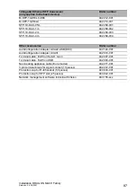
Page 87: ...24 001 AutoConfiguration Adapter ACA31 942 074 001 Terminal cable RJ45 on Sub D 9 pin 942 097 001 Terminal cable RJ45 on USB 942 096 001 Non heating appliance cable Euro model 942 271 001 3 pin terminal block for signal contact 10 pieces 942 272 001 Protection cap for RJ45 socket 50 pieces 943 936 001 Protection cap for SFP slot 25 pieces 943 942 001 Network management software Industrial HiVision...

Page 88: ...nput current 16 A per conductor EN 61000 3 3 Electromagnetic compatibility EMC part 3 3 Threshold values limitation of voltage changes voltage fluctuations and flickering in public low power supply networks for devices with a rated current 16 A per conductor that are not subject to any special connection condition EN 61000 6 2 Electromagnetic compatibility EMC Part 6 2 Generic standards Immunity f...

Page 89: ...hmann Competence Center is ahead of its competitors on three counts with its complete range of innovative services Consulting incorporates comprehensive technical advice from system evaluation through network planning to project planning Training offers you an introduction to the basics product briefing and user training with certification You find the training courses on technology and products c...

Page 90: ......

Reviews: