Central Switching Module PTN-CSM310-A/PTN-CSM540-A 7
Release 03 05/2020
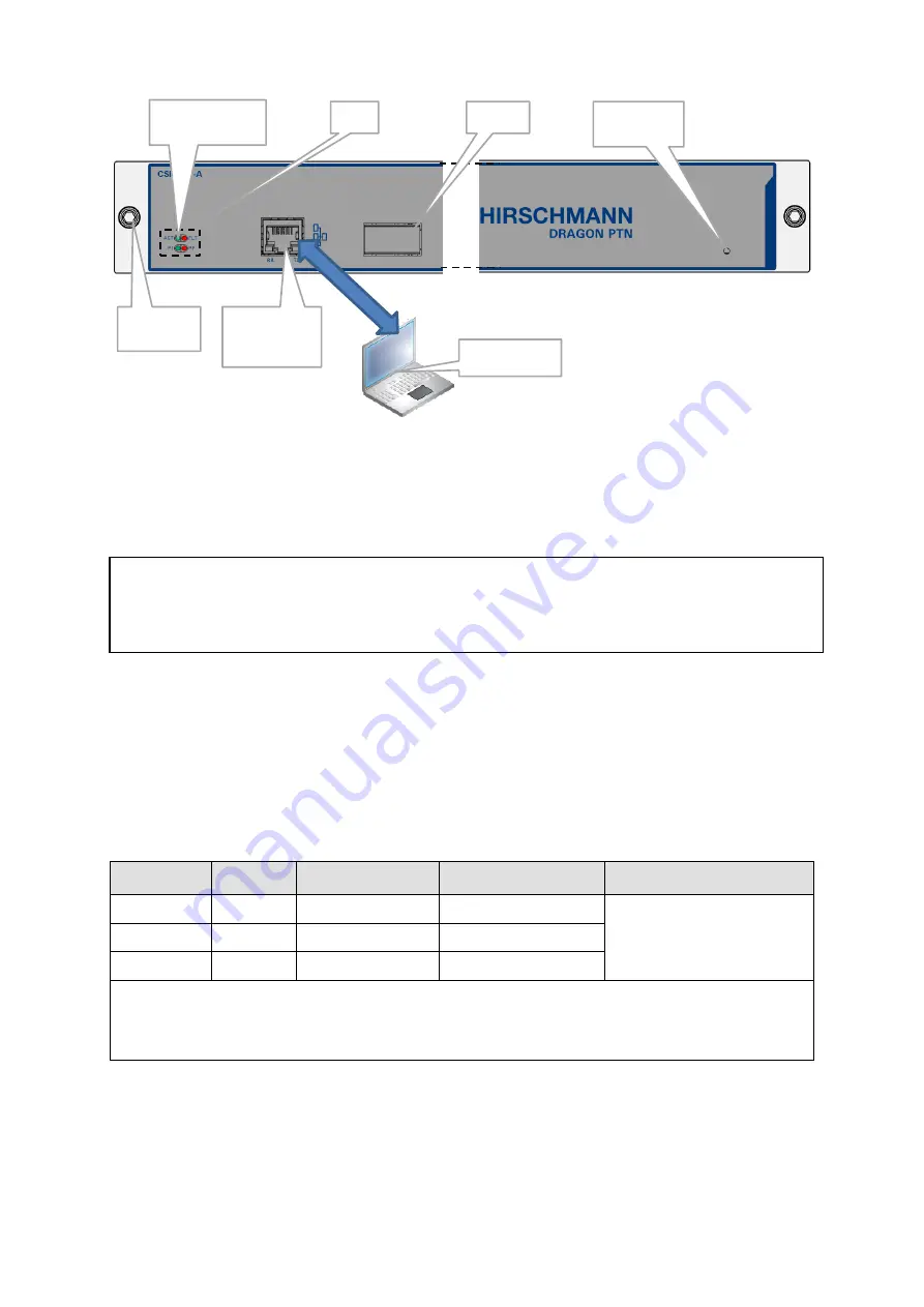
Figure 2
Front Panel CSM540-A In Core Node
2.1.1
Insert/Remove Module into/from Node
See ‘
Dragon PTN
Installation and Operation Manual’ Ref.[
1] in Table 2.
CAUTION:
1) Do not touch the heat sink when the CSM is in operation, or when removing the CSM
from the node. It can be extremely hot. Risk of getting burned!
2) The CSM could be heavier than expected because of the heat sink.
2.1.2
LEDs
The meaning of the LEDs depends on the mode of operation (= boot or normal) in which the
CSM module currently is running. After plugging in the module or rebooting it, the module
turns into the boot operation, see Table 3. After the module has rebooted successfully, the
module turns into the normal operation, see LEDs in Table 4.
Table 3
LED Indications In Boot Operation
Cycle
PI
PF
FLT
ACT LED
1
✓
---
Slow blinking
✓
(=active CSM)
or
--- (=standby/passive CSM)
2
✓
---
Fast blinking
3
✓
---
---
✓
: LED is lit ; --- : LED is not lit; The sub cycle times may vary.
The entire boot cycle time [1
→
3] takes approximately 5 minutes.
The node is reachable again when it can be discovered and measured by HiProvision (=Dragon PTN Management System,
see also Ref. [2Net] in Table 2);
LEDs
Display
HiProvision
Management
Connector
HiProvision PC
CSM
active/standby LED
Socket Head
Cap Screw
Hidden Reset
Button


