background image

41 

EESX20 and EESX30 


Release 1.5   04/2020 


Parameter 
 

min. 

typ. 

max. 

Unit 

Storage temperature  
 

-40 


+80 

°C 
 

Humidity (non-condensing)  
preliminary 

 10 


  85 


Air-pressure by operating  
 

795 
(+2000 m 
a.s.l) 


hPa 
 

Air-pressure by storage  
preliminary  

620 
(+4000 m 
a.s.l) 


hPa 
 

Table 5-6: Miscellaneous  


Board Weights 

Name 

Net weight 
 

EESX20 

42 g 

EESX30 

42 g 

EESX-Evaluation-Board 

370 g 

Table 5-7: Board Weights  


Ambient Air Temperature


EESX20/30 module  

Product  

Comment 

Operating Ambient Air Temperature  

EESX20/30 module  

- 40°C (16h) 

1) 


+ 85°C (16h) 

1)  


Non Operating Ambient Air Temperature  

EESX20/30 module  

˗  40°C (16h) 

1) 


+ 85°C (16h) 

1)  


Damp Heat 


EESX20/30 module  

+ 55 °C/ + 25 °C,  

12h 

– 12h, 2 cycles  

Table 5-8: Ambient temperature conditions (tested on EESX-Evaluation-Board)  

Note:

 The items marked with 

1) 

 means ambient air temperature.  


EESX-Evaluation-Board  

Product  

Comment 

Operating Ambient Air Temperature  

EESX-Evaluation-Board  

+   5°C 

1) 


+ 40°C 

1)  


Non Operating Ambient Air Temperature 


EESX-Evaluation-Board  

˗  40°C (16h) 

1) 


+ 85°C (16h) 

1)  


Note:

 The items marked with 

1) 

 means ambient air temperature.  

Summary of Contents for HIRSCHMANN EESX Series

Page 1: ...EESX20 and EESX30 Technical Support Release 1 5 04 2020 https hirschmann support belden eu com EESX Hardware Integration Guide Embedded Ethernet Switch eXtended Product Family EESX20 and EESX30 ...

Page 2: ...enclosed CD applies The performance features described here are binding only if they have been expressly agreed when the contract was made This document was produced by Hirschmann Automation and Control GmbH according to the best of the company s knowledge Hirschmann reserves the right to change the contents of this document without prior notice Hirschmann can give no guarantee in respect of the c...

Page 3: ...ponents to be cooled on EESX Module 18 2 2 PIN Assignment at connector CO201 19 2 3 PIN Description for connector CO201 21 2 4 PIN Assignment at connector CO202 22 2 5 PIN Description for connector CO202 23 3 Application Guide Line 24 3 1 Ethernet interface for 10 100Base TX connection 24 3 2 Ethernet interface for 1000Base TX 25 3 3 Ethernet interface for 100Base FX 25 3 3 1 Interface Connection ...

Page 4: ...7 3 Capacitive Coupling 1000Base FX 34 3 7 4 Magnetics Coupling 1000Base TX 35 3 8 Layout recommendations 35 3 9 Recommended Magnetic 36 4 Heat sink 37 4 1 Permissible operating temperature 37 4 2 Estimation of heat sink s cooling performance 38 5 Technical Data 39 6 Further Support 43 ...

Page 5: ... 1 2 in Guide for the EMC Directive 2004 108 EC 21st May 2007 The manufacturer or distributor of the end device in which the EES was installed is responsible for adhering to the applicable EU directives as well as the CE marking The EMC tests were performed in combination with the Evaluation Board Maintenance When designing this device Hirschmann was largely able to forego using wear parts The par...

Page 6: ...e characteristics of the recommended accessory parts may differ from the appropriate product This might limit the possible operating conditions for the entire system References On the EESX Development Kit CD you can find additional documents for the EESX Evaluation Board It is recommended to use these documents when developing your application EESX Evaluation Board schematics in PDF format EESX Ev...

Page 7: ...ransceivers 4 2 x DSC adapter for 100Base FX transceivers at FE Port 1 and GE Port 1 5 2 x Magnetics RJ45 connector for 10 100 1000Base TX 6 2 x SFP cages for 1000 100Base FX transceivers 7 Mode switches to set hardware mode to Base TX Copper or to Base FX optical fibre 8 LEDs for module status 9 LEDs for status information of link and data activity per port as well for device status 10 12 pin hea...

Page 8: ...tion Board 1 2 Power supply Connect the DC jack on the EESX Evaluation Board to a 24 VDC power supply Connect pins 1 4 of the jack to UE and the center pins 2 3 of the jack to GND Figure 1 3 DC jack connection The nominal voltage of the EESX Evaluation Board is 24V DC but also the EESX Evaluation Board can be supplied with 18 V up to 30 V at UE1 and or UE2 Supply the EESX Evaluation Board only ins...

Page 9: ...de 100 Mbit s full duplex mode 10 Mbit s half duplex mode 10 Mbit s full duplex mode Default configuration auto negotiation enabled Note EESX20 Ports 1 to 8 support Fast Ethernet e g 10 100 Base T TX full or half duplex EESX30 Ports 1 and 2 support Gigabit Ethernet e g 10 100 1000 Base T TX full or half duplex Ports 3 to 10 support Fast Ethernet e g 10 100 Base T TX full or half duplex Figure 1 4 ...

Page 10: ...elopment Find the contact data of the service in the last chapter of this manual Figure 1 6 FE Port 1 with DSC transceiver for 100Base FX 1 5 Mode switch Settings for Ethernet Ports Each Fast Ethernet port FE can operate in either 10 100Base TX using RJ45 connectors or 100Base FX mode using the SFP port selected by the two Mode switches see Figure 1 7 The Gigabit Ethernet ports GE can operate in e...

Page 11: ...Board and Logical Port means the numbering by the software EESX Evaluation Board Physical Port EESX20 Module Logical Port EESX30 Module Logical Port GE Port 1 Not available Port 1 GE Port 2 Not available Port 2 FE Port 1 Port 1 Port 3 FE Port 2 Port 2 Port 4 FE Port 3 Port 3 Port 5 FE Port 4 Port 4 Port 6 FE Port 5 Port 5 Port 7 FE Port 6 Port 6 Port 8 FE Port 7 Port 7 Port 9 FE Port 8 Port 8 Port...

Page 12: ... indicates abnormal operation status SWBOOT1 Off Green Software is not loading Software is loading GE Port 1 2 Off Green Off Yellow blinking No link no physical connection Link is up physical connection available No data traffic Data traffic FE Port 1 8 Off Green Off Yellow blinking No link Link is up No data traffic Data traffic Table 1 2 LED status indication 1 8 Measuring Point Connectors The 1...

Page 13: ...9 Socket RS232 A serial data RS232 V24_TxD RxD connection is available on the EESX Evaluation Board to provide access to the EESX module This enables you to set up a connection to the Command Line Interface CLI and system monitor For more information on the CLI functionality refer to the Command Line Interface EES Reference Manual The serial interface uses RS232 V 24 without hardware handshake A S...

Page 14: ...vailable on the EESX Evaluation Board Push button SW401 to signal Ue_Ok Resets the EESX module if button pushed See 16 in Figure 1 1 Push button SW402 to signal PGOOD_PLD See 17 in Figure 1 1 Tracks the signal PGOOD_PLD to ground GND potential if button pushed This button is for test purposes ...

Page 15: ...EESX Evaluation Board are manufactured by TE Connectivity www te com Part number Connector male 120 pins 5084614 5 Package Tube or 5 5177986 5 Package Tape and Reel Connector male 80 pins 5084614 3 Package Tube or 5 5177986 3 Package Tape and Reel A stacking height of 5 mm is obtained as illustrated in Figure 2 2 at some positions less than 3 mm due to high components ...

Page 16: ...020 Figure 2 2 EESX module mounted on EESX Evaluation Board with screws and nuts sectional drawing Note It is recommended for costumer s applications to let the space idle beneath the module board for better heat dissipation of the module ...

Page 17: ...der The figure below shows the position of the drill holes for the screws of the cooling block and the total height of the module For details about the Heat dissipation parameters see chapter Heat sink Figure 2 3 EESX module with mounted cooling plate Bottom side and top view ...

Page 18: ... board for a heat sink In the picture below are the positions of the components on EESX board which should be connected to a heat sink for cooling Figure 2 4 Positions of ICs to be cooled on EESX Module TOP VIEW Component heights on ESSX board for a heat sink Component Height min Height nominal Height max IC401 2 20 mm 2 33 mm 2 52 mm IC901 Not available Not available 1 60 mm IC902 Not available N...

Page 19: ...5 SPI_MOSI_Aux 26 Reset_in 27 LOS_P8 28 LOS_P7 29 LOS_P6 30 LOS_P5 31 LOS_P4 32 LOS_P3 33 LOS_P2 34 LOS_P1 35 LED_Lnk_Act_P8 36 LED_Lnk_Act_P7 37 LED_Lnk_Act_P6 38 LED_Lnk_Act_P5 39 LED_Lnk_Act_P4 40 LED_Lnk_Act_P3 41 LED_Lnk_Act_P2 42 LED_Lnk_Act_P1 43 LED_Speed_P8 44 LED_Speed_P7 45 LED_Speed_P6 46 LED_Speed_P5 47 LED_Speed_P4 48 LED_Speed_P3 49 LED_Speed_P2 50 LED_Speed_P1 51 I2C_Clk_P8 52 I2C_...

Page 20: ...ND 92 GND 93 TD P5 94 RD P5 95 TD P5 96 RD P5 97 GND 98 GND 99 TD P4 100 RD P4 101 TD P4 102 RD P4 103 GND 104 GND 105 TD P3 106 RD P3 107 TD P3 108 RD P3 109 GND 110 GND 111 TD P2 112 RD P2 113 TD P2 114 RD P2 115 GND 116 GND 117 TD P1 118 RD P1 119 TD P1 120 RD P1 Table 2 2 Pin assignment of interface connector CO201 ...

Page 21: ...Control signal of LED System ready low active LED_Alarm Output LVTTL Control signal of LED Alarm low active SPI_MISO_Aux Input LVTTL MISO line of SPI bus to the CPLD chip SPI_MOSI_Aux Output LVTTL MOSI line of SPI bus to the CPLD chip Relay_Control Output LVTTL Signal for Relay control Reset_in Input LVTTL Module reset low active LOS_P 1 8 Logical signal LVTTL Loss of signal for port 1 to 8 for op...

Page 22: ...P_Present_EES_G1 22 SD_ WP 23 GND 24 GND 25 LOS_G2 26 SD_ CD 27 LOS_G1 28 Logic_Spare4 29 GND 30 GND 31 Logic_Spare2 32 Logic_Spare1 33 Config_G11 34 Config_G21 35 Config_G12 36 Config_G22 37 GND 38 GND 39 SD_Dis_VCC 40 Reset_USB_Hub 41 VCC_Backup 42 VCC_Backup 43 GND 44 GND 45 PMDX1 G1 46 PMDX0 G1 47 PMDX1 G1 48 PMDX0 G1 49 GND 50 GND 51 PMDX3 G1 52 PMDX2 G1 53 PMDX3 G1 54 PMDX2 G1 55 GND 56 GND ...

Page 23: ... optical transceivers LOS_G 1 2 Logical signal LVTTL Signal Loss Of Signal at Gigabit Ports 1 and 2 high active for optical transceivers Config_G 11 12 21 22 Logical signal LVTTL Selection of a certain System configuration Currently without function Reset_USB_Hub Input LVTTL Reset of USB Hub low active VCC_Backup Power Backup of VCC for Real time clock on EESX module Backup capacitor on Evaluation...

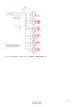
Page 24: ...tion of the Ethernet and SPI interfaces 3 1 Ethernet interface for 10 100Base TX connection Figure 3 1 10 100Base TX interface recommandation Table 3 1 10 100Base TX center tap voltage For operational reasons the ports require different supply voltages for the center taps of the magnetic poles See table 3 1 for details ...

Page 25: ...t interface for 1000Base TX Figure 3 2 1000Base TX interface recommandation 3 3 Ethernet interface for 100Base FX 3 3 1 Interface Connection SFP Transceiver Figure 3 3 100Base FX SFP interface recommandation Table 3 2 100Base FX SFP schematic information ...

Page 26: ... EESX20 and EESX30 Release 1 5 04 2020 3 3 2 Interface connection 1 9 Transceiver Figure 3 4 100Base FX 1 9 transceiver interface recommendation Table 3 3 100Base FX 1 9 transceiver schematic information ...

Page 27: ...27 EESX20 and EESX30 Release 1 5 04 2020 3 4 Ethernet interface for 1000Base FX 3 4 1 Interface Connection SFP Transceiver Figure 3 5 1000Base FX SFP interface recommandation ...

Page 28: ...04 2020 3 4 2 Interface connection 1 9 Transceiver Figure 3 6 1000Base FX 1 9 transceiver interface recommendation The feature 1 9 Transceiver is currently not supported for the Gigabit ports 1 and 2 Use the Fast Ethernet ports instead ...

Page 29: ...aster device to synchronize the data transfer SPI_MOSI Serial Data Output SPI data master out slave in SPI_MISO Serial Data Input SPI data master in slave out With respect to the EESX module Table 3 4 SPI connector pin assignment It is recommended to use a CPLD chip for communication between EESX module and its outer periphery The logic file of the CPLD chip on the EESX Evaluation Board is availab...

Page 30: ...30 EESX20 and EESX30 Release 1 5 04 2020 Figure 3 7 SPI implementation example as alternative for the CPLD chip ...

Page 31: ...reads status information from the host system on SPI_MISO_Aux providing of SFP transceivers is installed Bit Signal name Description 31 30 SW_Init_Phase 1 0 Software initializing during boot phase 29 22 LED_gr_P 8 1 Link status for FE Ports 8 1 on Evaluation Board green LEDs high link low no link 21 20 LED_gr_G 2 1 Link status for GE Ports 2 1 on Evaluation Board green LEDs high link low no link 1...

Page 32: ...s connected to a SFP transceiver This connection is only required for the 100Base FX mode in which a SFP transceiver is used This interface can be used to read transceiver status information such as transceiver type temperature optical receive power and other information provided by the selected SFP transceiver In addition the I2C_Clk_x pins are used to pre set the port mode during start up If a h...

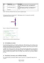
Page 33: ...be coupled directly with a capacitor 100 nF for all ports in FX Mode see Figure 3 10 if the capacitors are not implemented in the used SFP and 1 9 transceivers On the host device side the circuit is dependent of the used PHY component Please refer to the data sheet of the appropriate PHY vendor Figure 3 10 Capacitive Coupling Circuit Diagram 3 7 2 Magnetics Coupling 10 100Base TX The Ethernet sign...

Page 34: ...34 EESX20 and EESX30 Release 1 5 04 2020 Figure 3 11 Magnetics Coupling Circuit Diagram 3 7 3 Capacitive Coupling 1000Base FX Figure 3 12 Capacitive Coupling Circuit Diagram ...

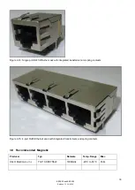
Page 35: ...IC808 for ports 5 to 8 Connect the signal pathes coming from the switching IC directly to the TX or FX port B Ethernet Jack for twisted pair Use Ethernet Jacks with spring contacts for twisted pair copper mode to improve galvanic contact to metal housing due to EMC reasons C Ethernet Jack with integrated transformer for twisted pair Use RJ45 Ethernet Jacks with integrated transformers to reduce sp...

Page 36: ...thernet Jack with integrated transformer and spring contacts Figure 3 15 4 port RJ45 Ethernet Jack with integrated transformers and spring contacts 3 9 Recommended Magnetic Producer Typ Datarate Temp Range Misc HALO Electronics Inc TG110 HPE7N5LF 100Mbit s 40 C to 85 C PoE ...

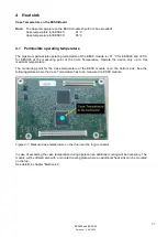
Page 37: ...g point of the Case Temperature Operate the device only up to this maximum temperature The measuring point for the Case temperature of the EESX module is on the bottom side See the following picture where the Case Temperature has to be measured on ESSX module Figure 4 1 Measure Case temperature on the chip near the long connector In case of exceeding the case temperature during operation an additi...

Page 38: ...de additional cooling for the device WARNING FIRE HAZARD Exceeding the maximum permissible operating temperature can cause the device to catch fire Failure to follow these instructions can result in death serious injury or equipment damage Example Heat dissipation with a cooling element The following calculation delivers an estimated expected module temperature based on ambient temperature Formula...

Page 39: ...Description min typ max Unit VCC24 Supply voltage EESX Evaluation Board DC 18 24 30 V VCC3 3 Supply voltage EESX 3 3 5 3 3 3 3 5 V VCC3 3 Maximum Ripple EESX AC 50 mVpp PIN VCC3 3 Power Consumption EESX module only EESX20 EESX30 5 7 W W PIN VCC24 Power Consumption EESX Evaluation Board with EESX30 module Tx mode Fx mode depends from plugged SFP modules 8 1 12 5 W W Table 5 2 Power supply and power...

Page 40: ...o peak 0 5 2 4 Vpp Output resistance 100 Input resistance 100 Table 5 4 Electrical Specification Ethernet Fx lines Symbol Description min typ max Unit fmax SPI Clock Frequency SPI 1 16 MHz tsu Setup time SPI_MOSI before SPI_Clk 40 ns SPI_Clk before SPI_En1 40 ns SPI_En2 before SPI_Clk 40 ns SPI_MISO before SPI_Clk 20 ns Parallel Data Input before SPI_En2 20 ns th Hold time SPI_MOSI after SPI_Clk 2...

Page 41: ... module Product Comment Operating Ambient Air Temperature EESX20 30 module 40 C 16h 1 85 C 16h 1 Non Operating Ambient Air Temperature EESX20 30 module 40 C 16h 1 85 C 16h 1 Damp Heat EESX20 30 module 55 C 25 C 12h 12h 2 cycles Table 5 8 Ambient temperature conditions tested on EESX Evaluation Board Note The items marked with 1 means ambient air temperature EESX Evaluation Board Product Comment Op...

Page 42: ...d in operation Due to possible hot spots of electronical components especially the case of integrated circuits MTBF Product Standard Comment MTBF Value EESX20 207 4 years Gb 25 C 87 2 years Gb 60 C EESX30 198 6 years Gb 25 C 85 1 years Gb 60 C Table 5 9 MTBF values of the EESX module according Telcordia SR332 ...

Page 43: ...ail inet ap belden com Hirschmann Competence Center The Hirschmann Competence Center is ahead of its competitors Consulting incorporates comprehensive technical advice from system evaluation through network planning to project planning Training offers you an introduction to the basics product briefing and user training with certification The current training courses to technology and products can ...

Reviews: