52
Installation GRS1020/1120/1030/1130
Release 04 01/2020
For
every
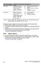
supply voltage to be connected, perform the following steps:
Remove the terminal connector from the device.
Connect the wires according to the pin assignment on the device with the
clamps.
Fasten the wires in the terminal block by tightening the terminal screws.
You find the prescribed tightening torque in chapter:
“General technical data” on page 60
2.5.3
Signal contact
Connect the signal contact lines with the terminal block connections.
Fasten the wires in the terminal block by tightening the terminal screws.
You find the prescribed tightening torque in chapter:
“General technical data” on page 60
Type of the voltages
that can be connected
Specification of the supply
voltage
Pin assignment
DC voltage
Rated voltage range
110 V DC ... 250 V DC
Voltage range incl.
maximum tolerances
88 V DC ... 288 V DC
+/L
-/N
Plus terminal of the supply
voltage
Minus terminal of the supply
voltage
Protective conductor
AC voltage
Rated voltage range
110 V AC ... 240 V AC,
50 Hz ... 60 Hz
Voltage range including
maximum tolerances
88 V AC ... 276 V AC,
47 Hz ... 63 Hz
+/L
-/N
Outer conductor
Neutral conductor
Protective conductor
Table 27: Supply voltage with characteristic value M: type and specification of the
supply voltage, pin assignment on the device
Summary of Contents for HIRSCHMANN GREYHOUND GRM Series
Page 80: ......

