Installation OCTOPUS OS20/OS24 Managed
Release 10 08/2017
21
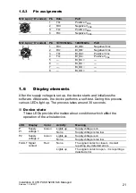
1.5.3
Pin assignments
1.6
Display elements
After the supply voltage is set up, the device starts and initializes the
software. Afterwards, the device performs a self-test. During this process,
various LEDs light up. The process takes around 30 seconds.
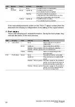
Device state
These LEDs provide information about conditions which affect the
operation of the whole device.
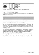
M12 4-pin (“D”-coded)
Pin
Data
PoE
1
TX+
Positive V
PSE
2
RX+
Negative V
PSE
3
TX
−
Positive V
PSE
4
RX
−
Negative V
PSE
M12 8-pin (“X”-coded)
Pin
10/100 Mbit/s
1000 Mbit/s
PoE
1
RX+
BI_DB+
Negative V
PSE
2
RX
−
BI_DB
−
Negative V
PSE
3
TX+
BI_DA+
Positive V
PSE
4
TX
−
BI_DA
−
Positive V
PSE
5
—
BI_DC+
—
6
—
BI_DC
−
—
7
—
BI_DD
−
—
8
—
BI_DD+
—
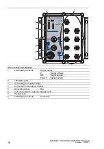
LED
Display
Color
Activity
Meaning
P
P1
Supply
voltage 1
Green
Lights up
Supply voltage is on
None
Supply voltage is too low
P2
Supply
voltage 2
Green
Lights up
Supply voltage is on
None
Supply voltage is too low
FAULT Signal
contact
Red
None
The signal contact is closed - it is
not
reporting any detected errors.
Lights up
The signal contact is open - it is reporting a
detected error.
1
2
3
4
1
8
2
3
6
7
4
5
Summary of Contents for HIRSCHMANN OCTOPUS OS20 Series
Page 45: ...Installation OCTOPUS OS20 OS24 Managed Release 10 08 2017 45 ...
Page 46: ......


