32
Installation OCTOPUS OS20/OS24 Managed
Release 10 08/2017
2.5
Connecting the supply voltage
Use a back-up fuse suitable for the supply network.
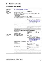
See “General technical data” on page 37.
Do not use connectors as electrical isolating devices.
Make sure that the disconnecting device is easily accessible for
disconnecting the device from the mains voltage.
Connect the power supply connector to the power supply socket of the
device.
2.6
Operating the device
When you connect the supply voltage, you start up the device.
2.7
Connecting data cables
You have the option to connect end devices or other segments to the ports
of the device via twisted pair cables.
Note the following general recommendations for data cable connections in
environments with high electrical interference levels:
Keep the length of the data cables as short as possible.
Use optical data cables for the data transmission between the buildings.
When using copper cables, provide a sufficient separation between the
power supply cables and the data cables. Ideally, install the cables in
separate cable channels.
Verify that power supply cables and data cables do not run parallel over
longer distances, and that ideally they are installed in separate cable
channels. If reducing the inductive coupling is necessary, verify that the
power supply cables and data cables cross at a 90° angle.
Use SF/UTP cables as per ISO/IEC 11801:2002.
Use a shielded CAT5 cable or better.
Use a shielded 4-pin M12 plug.
Connect only PoE-supplier devices whose data connections are located
in the interior of the building and are specified as SELV circuits.
There is no galvanic separation between the PoE ports of an OCTOPUS
OS24 device. If you are using these devices in ring structures, wire a PoE
port with a non-PoE port to avoid a potential difference.
Summary of Contents for HIRSCHMANN OCTOPUS OS20 Series
Page 45: ...Installation OCTOPUS OS20 OS24 Managed Release 10 08 2017 45 ...
Page 46: ......

