


4.2 Star topology
21
4 Network topologies
OZD Profi G12D... ATEX 1 V. 03 07/2014
4.2 Star topology
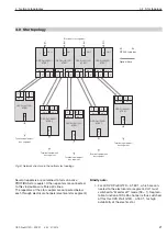
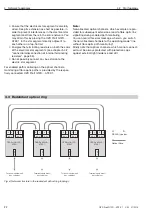
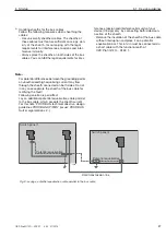
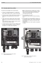
Fig. 5: Network structure in the optical star topology
CH 2
SE
CH 3
SE
CH 2
SE
CH 3
SE
CH 2
S
E
CH 2
S
E
CH 2
S
E
CH 2
S
E
CH 2
S
E
CH 2
S
E
CH 2
S
E
CH 2
S
E
CH 2
S
E
CH 2
S
E
Terminal equipment/
bus segment
Terminal equipment/
bus segment
Terminal equipment/
bus segment
Terminal equipment/
bus segment
Terminal equipment/
bus segment
OZD Profi G12D...
ATEX 1
CH 1
CH 2
SE
CH 3
SE
OZD Profi G12D...
ATEX 1
CH 1
CH 2
SE
CH 3
SE
OZD Profi G12D...
ATEX 1
CH 1
OZD Profi G12D...
ATEX 1
CH 1
OZD Profi G12D...
ATEX 1
CH 1
OZD Profi G12D...
ATEX 1
CH 1
OZD Profi G12D...
ATEX 1
CH 1
OZD Profi G12D...
ATEX 1
CH 1
OZD Profi G12D...
ATEX 1
CH 1
Electrical star segment
S0 = 1
S0 = 1
S0 = 1
S0 = 1
RS 485-type bus
Optical fibre
Several repeaters are combined to form an active
PROFIBUS star coupler. Other repeaters are connected
to this via double-wire fibre optic lines.
The repeaters of the star coupler are connected below
each through electrical channels (electrical star segment).
Kindly note:
For all OZD Profi G12D... ATEX 1, which are con-
nected to the electrical star segment, CH1 must
switched to “Monitor off“ mode (S0 = 1). Segmen-
tation function of RS 485 channel is thus switched
off for this OZD Profi G12D... ATEX 1, for high
availability of the electric star.


