4 Network topologies
4.2 Star topology
22
OZD Profi G12D... ATEX 1 V. 03 07/2014
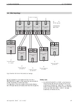
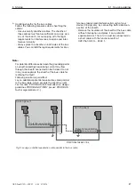
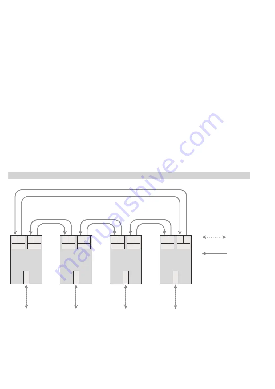
Fig. 6: Network structure in the redundant optical ring topology
RS 485-type bus
Optical fibre
Terminal equipment/
bus segment
OZD Profi G12D...
ATEX 1
CH 1
CH 3
S
E
CH 2
S
E
Terminal equipment/
bus segment
OZD Profi G12D...
ATEX 1
CH 1
CH 3
S
E
CH 2
S
E
Terminal equipment/
bus segment
OZD Profi G12D...
ATEX 1
CH 1
CH 3
S
E
CH 2
S
E
Terminal equipment/
bus segment
OZD Profi G12D...
ATEX 1
CH 1
CH 3
S
E
CH 2
S
E
4.3 Redundant optical ring
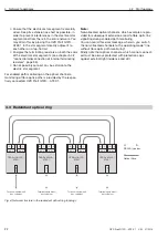
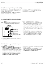
Ensure that the electrical star segment is carefully
wired. Keep its ex tension as short as possible, in
order to prevent interferences in the electrical star
segment and from there in the entire network. You
may attain this by placing the OZD Profi G12D...
ATEX 1 in the star segment directly adjacent to
each other on a top-hat rail.
Energise the terminating resistors on both the ends
of the electrical star segments (see chapter 5.4.2,
“connection/disconnection of internal terminating
resistors”, page 35).
Do not possibly connect any bus station to the
electric star segment.
For enabled path monitoring on the optical channels,
monitoring of fibre optic paths is provided by the respec-
tively connected OZD Profi G12D... ATEX 1.
Note:
Non-allocated optical channels, which example are pro-
vided for subsequent extensions, lead to fibre optic line
signalling during enabled path monitoring.
You can avoid this error message, wherein, you switch
the non-allocated channels to the operating mode “line
without fibre optic path monitoring”.
Kindly note that optical channels, which are not connect-
ed must be always protected with protection caps
against external light incidence and dirt.

