5.1 Design guidelines
27
5 Startup
OZD Profi G12D... ATEX 1 V. 03 07/2014
Handling sheaths for the bus cables
Follow the following measures when sheathing the
cables:
- Use universally sheathed cables. The sheaths of
these cables must feature sufficient coverage den-
sity of the sheath , for complying with the legal
requirements for interference emissions and inter-
ference immunity.
- Always place the sheaths on both sides of the bus
cables. You can fulfill the legal requirements for inter-
ference emission and interference immunity of your
device (CE sign) only by connecting both-sided con-
nection of the sheath.
- Remove the insulation of the sheath of the bus cable
without interruption and place it on a potential
equalisation bar. This in turn must be connected via
a short cable with the functional earth of
OZD Profi G12D… ATEX 1.
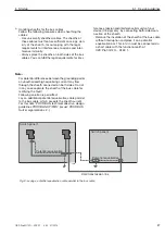
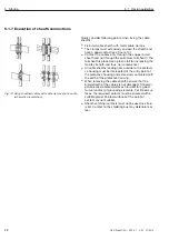
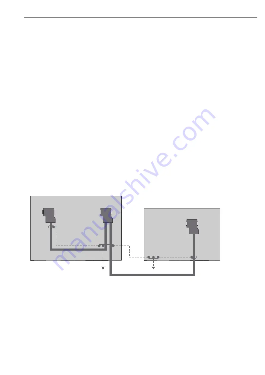
Data transmission line
Potential equalisation
Potential equalisation
Switch panel 1
Switch panel 2
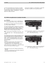
Fig. 9: Laying a potential equalisation cable parallel to the bus cable
Note:
For potential differences between the grounding points
an unauthorised high equalising current may flow
through the sheath connected on both sides. Do not
in any case separate the sheath of the bus cable for
rectifying the fault!
Following solution is permitted:
Lay an additional potential equalisation cable parallel
to the bus cable, which accepts the sheath current.
For this note “PROFIBUS, technical direc tive, design
guidelines PROFIBUS-DP/FMS” (issuer: PROFIBUS
Nutzer organisation e.V.).

