5.6 Connect electrical bus cables
37
5 Startup
OZD Profi G12D... ATEX 1 V. 03 07/2014
5.6 Connect electrical bus cables
z
Warning!
Work on ex-e cables in zone 1 is permitted only
with hot work permit or in the current-free state.
The repeaters are equipped with an electrical port with
RS 485 level.
The RS 485 bus cables are designed in the protection
class ex-e EN 60079-7:2007. They are placed on the
front side of the OZD Profi G12DU ATEX 1 on four sepa-
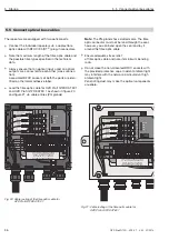
rate single terminals (DI A, DI B, DO A and DO B). The
terminals have a valid type approval certificate. The con-
nections are in duplicate in order to loop through the bus
cable through the device.
Note
: The terminals are accessible for OZD Profi … DK
… and OZD Profi … DE … after opening the protective
housing.
Note
: If the terminating resistors are not connected, data
cable is looped through without signal regeneration
through the device.
The RS 485 bus cables RxD/TxD–N and RxD/TxD–P are
galvanically separated (functional separation) vis-a-vis
the 24 V supply voltage within the SELV limits.
The RS 485 interface is galvanically connected to the
potential equalisaton connection.
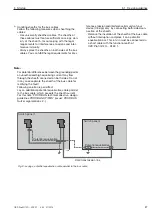
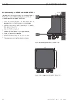
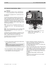
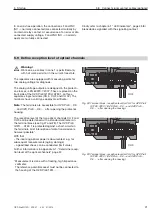
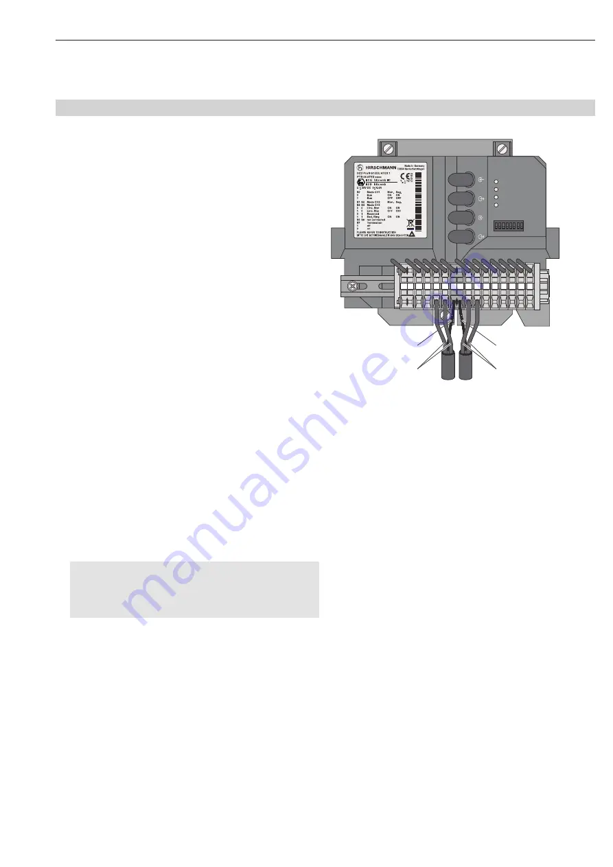
Connect the RS 485 bus cable and its cable shield to
the terminal block, see fig 22.
Note:
Ensure that bus segments connected to the 485
inter face are terminated on both the ends.
Use only shielded pair cables as RS 485 bus cable
Ensure adequate stress relief of RS 485 bus cable
and consider its minimum bending radii.
Remove RS 485 bus cable from OZD Profi, if no
device is connected on the other cable-end or the
same has been switched currentless.
The open cable otherwise works as an antennae and
can couple interferences.
Follow the following sequence when connecting a RS
485 bus cable to the OZD Profi G12D… ATEX 1 for an
active network, in order to minimise the disturbances :
attach 1. RS 485 bus connector to the device to be
connected (e.g. on the programming unit) and screw
on tightly.
2. Install RS 485 bus cables on OZD Profi G12D…
ATEX 1 .
Proceed in the reverse sequence when removing a
repeater from the network.
S0 S1 S2 S3 S4 S5 S6 S7
System
CH1
CH2
CH3
CH3
CH2
24
V*
24
V
DI
B
DI
A
0V
0V
FG FG
DO
B
DO
A
CH
0V
F
NC
F
NO
CH
3
CH
2
F
9
4
3881321000000001
Ser.
N
o.
:
0123
4
56
7
89
Shield
Incoming
Bus line
Outgoing
Bus line
Shield
Fig. 22: Terminal block - connections of the electrical bus
cables for OZD Profi G12DU ATEX 1
(OZD Profi ...DK ... and OZD Profi ... DE ... : after
opening the housing)


