5 Startup
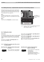
5.10 Connect operating voltage supply
42
OZD Profi G12D... ATEX 1 V. 03 07/2014
z
Warning!
Work on ex-e cables in zone 1 is permitted only
with hot work permit or in the current-free state.
The repeaters are equipped with a connection for two
independent operating voltages.
The supply voltage connection is designed in the ignition
protection ex-e EN 60079-7:2007. The connection cables
are placed on the front side of the
OZD Profi G12DU ATEX 1 on three separate single termi-
nals (24 V, 24 V* and 0V). The terminals have a valid type
approval certificate.
The 4 connections of the double terminal for the 0V con -
nection are galvanically connected to each other, colour
gray, ex-e.
Note
: The terminals are accessible for OZD Profi … DK
… and OZD Profi … DE … after opening the protective
housing.
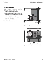
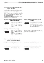
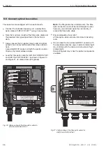
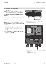
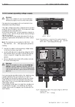
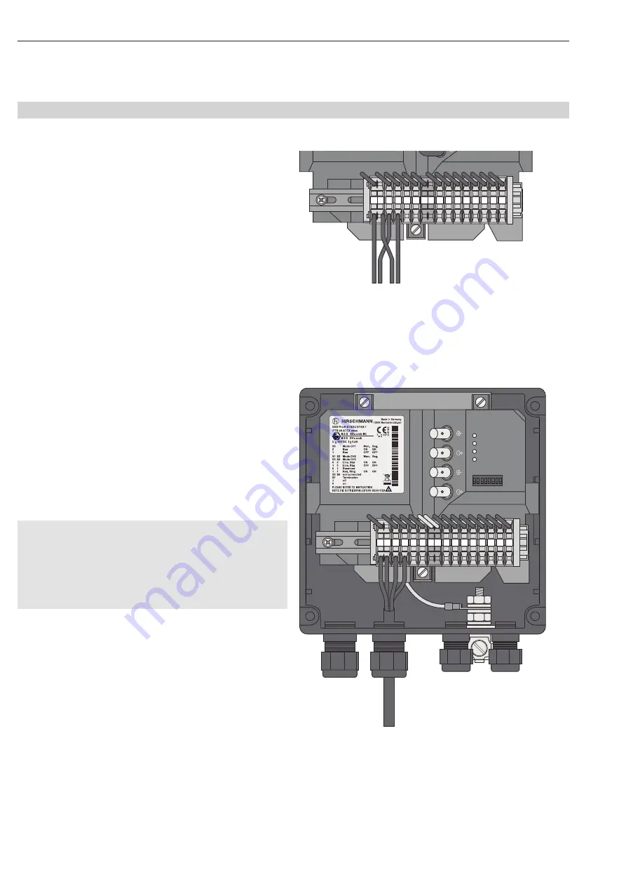
Connect the cables for the operating voltage supply
to the terminal block, see fig 30.
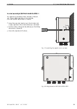
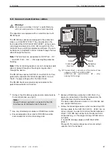
Lead the RS cable for the operating voltage for OZD
Profi G12DK ATEX 1 and OZD Profi G12DE ATEX as
shown in figure 31 through the cable entries (PG
glands).
Ensure adequate stress relief of the cables and note
its minimum bending radii.
z
Warning!
Supply the module only with a stable
safety low
voltage
as per IEC 950/EN 60 950/VDE 0805 of
m32 VDC (typ. +24 VDC). Voltage source
must comply with NEC, class 2 as per the UL/CSA
approval.
For increasing the operational safety, the module can be
supplied redundant through terminals 0 V and 24 V* .
At breakdown of the reg ul ar supply voltage the module
automatically switches to the redundant operating vol -
tage supply. There is no load distribution between indi-
vidual supply options.
The signalling contact does not signal the breakdown of
an individual 24 V supply. For monitoring, like the sig-
nalling contact, both the supplies must be placed on an
input module.
5.10 Connect operating voltage supply
24
V*
24
V
DI
B
DI
A
0V
0V
FG FG
DO
B
DO
A
CH
0V
F
NC
F
NO
CH
3
CH
2
F
0
V
/
+
2
4
V
0
V
/
+
2
4
V*
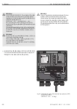
Fig. 30: Terminal block - connection of the supply voltage for
OZD Profi G12DU ATEX 1 (OZD Profi ...DK ... and OZD
Profi ... DE ... : after opening the housing)
S0 S1 S2 S3 S4 S5 S6 S7
Sys
te
m
C
H1
C
H
2
C
H
3
C
H
3
C
H
2
24
V*
24
V
DI
B
DI
A
0V
0V
FG FG
DO
B
DO
A
CH
0V
F
NC
F
NO
CH
3
CH
2
F
94388
1
32
1
00000000
1
S
e
r.
-No
.
: 0
1
23456789
Fig. 31: Cable lead-through of the supply voltage for OZD Profi
G12DK ATEX 1
(OZD Profi ... DE ... : analog)

