6.1 LED indicators
45
6 Troubleshooting
OZD Profi G12D... ATEX 1 V. 03 07/2014
6 Troubleshooting
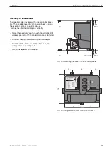
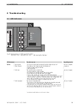
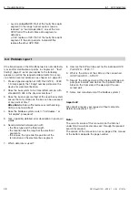
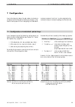
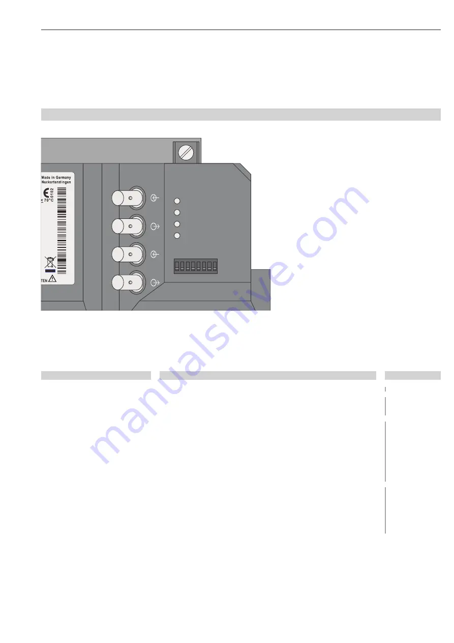
Fig. 32: LED indicators for OZD Profi G12DU ATEX 1
(OZD Profi ...DK ... and OZD Profi ... DE ... : after opening the housing)
S0 S1 S2 S3 S4 S5 S6 S7
Sys
te
m
C
H1
C
H
2
C
H
3
C
H
3
C
H
2
94388
1
32
1
00000000
1
S
e
r.
-No
.
: 0
1
23456789
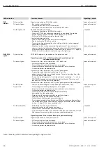
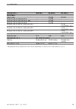
Possible reasons
– The transmission speed was detected and the voltage supply is ok
– Breakdown of the voltage supply (total breakdown*)
– Supply voltage wrongly connected
– Defective module
Transmission rate not yet detected
– No transmitting bus station available
– No connection to a telegram transmitting partner module
– Transmitting and receiving fibre optics are swapped
– Transmission rate does not comply with the PROFIBUS standard
– Only one active bus station is connected, which transmits token only to itself.
After connecting a second bus station the indicator must change (token tele -
grams alone are not adequate for setting the transmission rate).
– The connected RS 485 segment is closed only on one side
Transmission rate detected but
– The slot time of the network could not be determined (network parameter
HSA set very low, no transmitting bus station avail able)
– An optical channel is set at mode “redundant optical ring“, but not the sec-
ond one (this operating mode must be always set at both optical channels)
– The slot time of the network is set at a very low value
* for redundant supply breakdown of both supply voltages
LED indicators
System
glows green
does not glow
blinks red
blinks red/green
Signalling contact
does not respond
responds
does not respond
does not respond
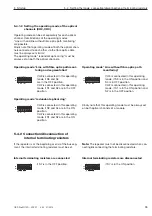
6.1 LED indicators

