background image

2 Safety

6

OZD Profi G12D... ATEX 1    V. 03  07/2014

Laws, standards or guidelines applicable for the usage
and/or the planned intended use must be complied with
just like the appropriate data sheets, declarations of con-
formity, EC-type examination certificates and certificates
where applicable.

Guideline 94/9 EC  must be observed for explosive haz-
ardous areas.

1.4 Relevant laws, standards, guidelines and other documentation

7

The devices comply with the regulations of the
 following European directive:

89/336/EEC 
Council directive for approximation of legal pro visio ns of
member states for electromagnetic compatibility
(changed  by directive 91/263/EEC, 92/31/EEC and
93/68/EEC).

Prerequisite for the compliance of EMC limits is the strict
compliance of guidelines specified in the description and
operating manual.

Records of the EC declarations of conformity are kept in
accordance with the above mentioned EC directive for
the compe tent authorities at:

Hirschmann Automation and Control GmbH
Stuttgarter Strasse 45-51
72654 Neckartenzlingen
Germany
Telefon

+49 (0)1805 14-1538

E-Mail

HAC.Support@Belden.com

The product is usable in the residential area (residential
area, business and commercial areas, small enterprises)
as well as in the industrial area.

– Interference immunity: 

EN 61000-6-2:2001

– Emitted immunity: 

EN 55022:1998+A1:2000+A2:2003 Class A

z

Note!

This equipment belongs to class A. This may

cause radio interference in the residential area. In this
case the operator may request execution of appropriate
measures and pay for the same.

Marking of devices

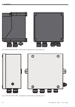
OZD Profi G12DU devices are marked as per EU-type
 examination certificate PTB 09 ATEX 2044 X as follows:

II 2 G Ex e mb op is [ib] IIC T4 Gb

OZD Profi G12DK and OZD Profi G12DE devices are
marked as per EU-type  examination certificate 
PTB 09 ATEX 2045 as follows:

II 2 G Ex e mb [ib] op is IIC T4

II 2 D Ex tD A21 IP 66 T 130 °C

1.5 Information on marking

Summary of Contents for Hirschmann OZD Profi G12DE ATEX 1

Page 1: ...imply a good Connection S0 S1 S2 S3 S4 S5 S6 S7 System CH1 CH2 CH3 CH3 CH2 24 V 24 V DI B DI A 0V 0V FG FG DO B DO A CH 0V F NC F NO CH 3 CH 2 F NICHT UNTER SPANNUNG ÖFFNEN DO NOT OPEN WHILE ENERGISED NE PAS OUVRIR SOUS TENSION NON APRIRE SOTTO TENSIONE NÃO ABRIR QUANDO ENERGIZADO 943881321000000001 Ser No 0123456789 ...

Page 2: ... manual are not a part of an earlier or existing agreement commitment or legal relationship or an amendment thereof All obligations of Hirschmann arise from the purchase contract which also include the com plete and exclusively applicable guarantee regulations These contractual warranty agreements are neither extended or limited by the versions of this operating man ual Moreover we would like to e...

Page 3: ...uction 13 3 General functions 17 3 1 Functions independent of the mode of operation 17 3 2 Functions dependent on the mode of operation 17 4 Network topologies 19 4 1 Line topology 19 4 1 1 Line topology with fibre optic path monitoring and segmentation 20 4 1 2 Line topology without fibre optic path monitoring 20 4 2 Star topology 21 4 3 Redundant optical ring 22 4 4 Combination with network topo...

Page 4: ...al terminating resistors 35 5 5 Connect optical bus cables 36 5 6 Connect electrical bus cables 37 5 7 Connect functional earth 39 5 8 Connect signal contact cables optional 40 5 9 Define reception level of optical channels 41 5 10 Connect operating voltage supply 42 5 11 Monitor LED indicators 43 6 Trouble shooting 45 6 1 LED indicators 45 6 2 Fault finding 47 6 3 Problem report 49 6 4 Contact ad...

Page 5: ...ay occur if the appropriate precautions are not taken z Warning means death seriousinjury or extensive damage to property may occur if appropriate precau tions are not taken z Caution means a minor injury or propertydamage may occur if appropriate precautions are not taken Note is important information on the product handling of the product or the respective part of documentation which must be pai...

Page 6: ...y are kept in accordance with the above mentioned EC directive for the competent authorities at Hirschmann Automation and Control GmbH Stuttgarter Strasse 45 51 72654 Neckartenzlingen Germany Telefon 49 0 1805 14 1538 E Mail HAC Support Belden com The product is usable in the residential area residential area business and commercial areas smallenterprises as well as in the industrial area Interfer...

Page 7: ...nel and system is not guaranteed if the component is not used in accordance with its intended purpose 1 6 Intended use 1 7 Assembly 1 7 1 General information on assembly Familiarise yourself with the device prior to assembly installation and startup and read this manual carefully The device must not be installed on places with aggres sive vapours Observe BGR A3 the Federal Institute for Geoscience...

Page 8: ...ned in zone 1 for servicing during ongoing operation Terminals in increased safety are covered The cover may be removed only if there is no explosion hazard circuits are switched to zero potential before hand 1 7 3 Assembly in zone 2 or zone 22 The devices must be installed in a housing with minimum protection class IP 54 as per gas ex in zone 2 For the assembly besides devices in housing design e...

Page 9: ...y with a safety low voltage as per IEC EN 60950 The optical fibres have an inherently safe optical radia tion and must be interconnected only with other inherent ly safe optical equipment For this preferably a similar device of type OZD Profi G12D ATEX 1 must be used Installation regulations as per IEC EN 60079 14 VDE 0165 1 for zone 1 or IEC EN 60079 15 for zone 2 as well as directive 99 92 EC mu...

Page 10: ...e cladding diameter of the fibre optic cable must be complied with for this see technical data cable glands page 54 Cable entries must be tightened for ensuring the required minimum protection class for this see technical data test torque page 55 Excessive tightening may impair the protection class When tightening the cap nut of the metal cable entries type E1WF e the gland must be secured against...

Page 11: ... ed In case of defect the device must be always replaced by an original one Check the packaging and contents for damage In case of damage notify the post and or the forwarding agent and the supplier Check the delivery scope based on the order and the delivery documents for completeness and correctness Preserve the original packaging The device should always be stored or transported in the original...

Page 12: ...2 Safety 12 OZD Profi G12D ATEX 1 V 03 07 2014 ...

Page 13: ...plosion protection The devices have been approved for operation in the explosion protection zones 1 21 2 and 22 as per AT They are thus interfaces between electrical Profibus sig nals from the explosion hazard areas ex area and the safe area non ex area The electronic circuits are separated by encapsulation as per EN 50028 VDE 0170 0171 part 9 from the explosive atmosphere The electrical connectio...

Page 14: ...roduction 14 OZD Profi G12D ATEX 1 V 03 07 2014 Fig 2 OZD Profi G12DK ATEX 1 with location of cable entries and grounding screw Fig 3 OZD Profi G12DE ATEX 1 with location of cable entries and grounding screw ...

Page 15: ...es are led outwards via PG cable glands The signalling contact connections are below each other and galvanically separated from the remaining electrical connections LEDs Four multi coloured LEDs signalise the current operating status and possible malfunctions Configuration The device is configured with eight easily accessible switches Fibre optics Use of fibre optics allows very large ranges and e...

Page 16: ...2 Introduction 16 OZD Profi G12D ATEX 1 V 03 07 2014 ...

Page 17: ...id During the installation at least one active bus station is required for checking the fibre optic connections This bus station is used as a source for telegrams After switching on the OZD Profi G12D ATEX 1 behave pas sively You can recognise the transmission speed from the telegrams transmitted by the bus station Optical startup aid is possible with the help of flashing channel LED Operating mod...

Page 18: ...e Repeater expects an echo If echo does not arrive after a specified time echomonitoring error is signalled with a red LED belonging to a channel Suppress echo The relevant receiver is separated from he remaining channels from the start of transmission of the telegram up to complete reception of the echo Segmentation If an echo monitoring error or distortion occurs on an optical channel the repeat...

Page 19: ...figuration Kindly note Individual terminal equipments or complete PROFIBUS segments with max 31 stations can be connected to OZD Profi G12D ATEX 1 Lay only fibre optic cables in severe EMC risk areas in order to rule out EMC influences in the entire network Optical channels which are connected to each other via fibre optic cable must have the same operating mode set 4 1 Line topology CH 2 S E CH 3...

Page 20: ...nt This is generally the case however it must be checked at occurrence of per manent communication interferences When configuring your network select possibly low bus station addresses in order to keep poten tial master time outs small For changing the settings kindly refer to the manufactur ers documentation related to connected terminal equip ment 4 1 2 Line topology without fibre optic path mon...

Page 21: ...fi G12D ATEX 1 CH 1 OZD Profi G12D ATEX 1 CH 1 OZD Profi G12D ATEX 1 CH 1 OZD Profi G12D ATEX 1 CH 1 OZD Profi G12D ATEX 1 CH 1 OZD Profi G12D ATEX 1 CH 1 Electrical star segment S0 1 S0 1 S0 1 S0 1 RS 485 type bus Optical fibre Several repeaters are combined to form an active PROFIBUS star coupler Other repeaters are connected to this via double wire fibre optic lines The repeaters of the star co...

Page 22: ...ng the OZD Profi G12D ATEX 1 in the star segment directly adjacent to each other on a top hat rail Energise the terminating resistors on both the ends of the electrical star segments see chapter 5 4 2 connection disconnection of internal terminating resistors page 35 Do not possibly connect any bus station to the electric star segment For enabled path monitoring on the optical channels monitoring ...

Page 23: ...ts small If there is redundancy e g line breakage it results into a switching time during which correct data trans mission may not be possible For ensuring shock free overbridging of the application it is recommended to set the number of repetitions retry of the telegram at minimum 3 for the PROFIBUS master For ensuring shock free switching back of the optical line to the optical ring after elimin...

Page 24: ... in the individ ual networks 4 4 Combination with network topologies of ex zone 2 22 RS 485 type bus Optical fibre Terminal equipment bus segment OZD Profi 12M PRO CH 1 CH 3 S E CH 2 S E Terminal equipment bus segment OZD Profi G12D ATEX 1 CH 1 CH 3 S E CH 2 S E Terminal equipment bus segment OZD Profi G12D ATEX 1 CH 1 CH 3 S E CH 2 S E Terminal equipment bus segment OZD Profi G12D ATEX 1 CH 1 CH ...

Page 25: ...ce types can be installed outside the ex area The housing cover may be opened for servicing during ongoing operation Terminals in increased safety are covered The cover may be removed any time during assembly in safe area 5 1 1 Assembly in zone 1 OZD Profi G12DU ATEX 1 devices shall be installed into an enclosure that complies with one of the following types of protection as a minimum accord ing t...

Page 26: ...s much more than the switched operating voltage These interference voltages may affect electronic devices The interference voltages of inductors must be limited to the emission source by switching with suppressors diodes or RC wiring Use only interference suppres sors which are intended for the relays or fans used by you Cabinet lighting Use bulbs for cabinet lighting e g LINESTRA lamps Avoid usin...

Page 27: ...of the bus cable without interruption and place it on a potential equalisation bar This in turn must be connected via a short cable with the functional earth of OZD Profi G12D ATEX 1 Data transmission line Potential equalisation Potential equalisation Switch panel 1 Switch panel 2 Fig 9 Laying a potential equalisation cable parallel to the bus cable Note For potential differences between the groun...

Page 28: ... sheaths leading from outside to the protecti ve housing must be intercepted at the entry point of the protective housing and extensively contacted with the earth of the protective housing When removing the cable sheaths ensure that the braid sheath of the cables is not damaged Tinned or galvanically stabilised surfaces are ideal for a good mutual contact of grounding elements For tinned sur faces...

Page 29: ... done in following steps Assemble disassemble repeater Setting the operating mode connecting disconnec ting the terminating resistors Connect optical bus cables Connect electrical bus cables Connect functional earth Connect signal contact cables optional Define reception level of optical channels Connect operating voltage supply Monitor LED indicators ...

Page 30: ... maintained Consider adequate space for the connection of bus and supply cables For easy installation of the optical fibre connect this to the repeater before the assembly Assemble the repeater on the top hat rail For this mount the top latch of the repeater on the top hat rail and press the lower side as shown in figure 11 on the rail till the latch engages Note You may disassemble the repeater f...

Page 31: ...embly location such that climatic limit values specified in the technical data are maintained Unscrew the pre assembled top hat rail adapter Drill three holes in the assembly plate as per the drilling dimensions in figure 14 Screw the repeater on the base Screw Spacer sleeve Washer Nut Screw Washer Nut Fig 13 Assembling the repeater on an assembly plate S0 S1 S2 S3 S4 S5 S6 S7 System CH1 CH2 CH3 C...

Page 32: ...assembly location such that climatic limit val ues specified in the technical data are maintained Drill four holes in the assembly plate as per the drilling dimensions in figure 16 Unscrew the housing cover Remove the four holders for the cover screws Screw the repeater on the base Reinstall the four holders for the cover screws If required screw on the housing cover again 141 152 Fig 16 Drilling ...

Page 33: ...on an even base It can be installed horizontally or vertically Select the assembly location such that climatic limit values specified in the technical data are maintained Drill two holes in the assembly plate as per the drilling dimensions in figure 18 Screw the repeater on the base 215 97 97 Fig 18 Drilling dimension OZD Profi G12DE ATEX 1 Screw Washer Fig 17 Assembling the repeater on an even ba...

Page 34: ...4 the operating mode of the optical channel CH3 is set With the DIP switch S7 the internal terminating resis tors are connected and disconnected 5 4 1 1 Setting the operating mode of the electri cal channel CH1 Operating mode electrical channel with segment monitoring CH1 is connected in this operating mode if S0 is in the OFF position Operating mode electrical channel without segment monitoring C...

Page 35: ...on and S4 is in OFF position CH2 is connected in this operating mode if S1 is in the ON position and S2 is in the OFF position S0 S1 S2 S3 S4 S5 S6 S7 CH1 CH2 CH3 1 2 3 4 5 6 7 8 ON OFF S0 S1 S2 S3 S4 S5 S6 S7 CH1 CH2 CH3 1 2 3 4 5 6 7 8 ON OFF Operating mode redundant optical ring CH3 is connected in this operating mode if S3 and S4 are in the ON position CH2 is connected in this operating mode i...

Page 36: ...uate stress relief of fibre optic cable and note its minimum bending radii Do not close the non allocated BFOC sockets with the provided protective caps Incident ambient light may interfere with the network particularly at high ambient light Penetrating dust may make the optical components unusable S0 S1 S2 S3 S4 S5 S6 S7 System CH1 CH2 CH3 CH3 CH2 24 V 24 V DI B DI A 0V 0V FG FG DO B DO A CH 0V F...

Page 37: ...al equalisaton connection Connect the RS 485 bus cable and its cable shield to the terminal block see fig 22 Note Ensure that bus segments connected to the 485 interface are terminated on both the ends Use only shielded pair cables as RS 485 bus cable Ensure adequate stress relief of RS 485 bus cable and consider its minimum bending radii Remove RS 485 bus cable from OZD Profi if no device is conn...

Page 38: ... building Otherwise lightning strikes in the area may destroy the repeater Establish the bus connections leave the building with fibre optic cable z Warning There is no galvanic separation between the bus cables and the functional earth connection Hence follow the following safetyinformation Do not connect the repeater via bus cables with system parts having a different earth potential The potenti...

Page 39: ...bles in zone 1 is permitted only with hot work permit or in the current free state The repeaters are equipped with connection for the func tional earth The functional earths are designed in the protection class ex e EN 60079 7 2007 It is placed on the front side of the OZD Profi G12DU ATEX 1 on a separate single termi nal FG The terminal has a valid type approval certifi cate Note For OZD Profi DK...

Page 40: ... and note its minimum bending radii z Warning Limit values of the relay contact maximum switching voltage 32 V maximum switching current 1 0 A maximum switching capacity 30 W Voltage connected to the relay must be a safety low voltage as per IEC 950 EN 60 950 VDE 0805 and according to the UL CSA approval must com ply with the regulations of NEC class 2 Kindly ensure correct connection allocation o...

Page 41: ...tical power is documented e g for subsequent measurements aging damage a good bad check can be conducted limit value Further information is in appendix A 1 Determine recep tion level of the optical channels page 57 Measurement is done with a floating high impedance voltmeter The reference potential socket must not be connected to the housing of the OZD Profi 12M 5 9 Define reception level of optic...

Page 42: ...s relief of the cables and note its minimum bending radii z Warning Supply the module only with a stable safety low voltage as per IEC 950 EN 60 950 VDE 0805 of maximum 32 VDC typ 24 VDC Voltage source must comply with NEC class 2 as per the UL CSA approval For increasing the operational safety the module can be supplied redundant through terminals 0 V and 24 V At breakdown of the regular supply v...

Page 43: ...of OZD Profi G12DU ATEX 1 You can find the meaning in chapter 6 1 LED indicators page 45 Note For OZD Profi DK and OZD Profi DU the LEDs are visible after opening the protective housing Note For the OZD Profi DK a housing cover with a window is provided as an accessory so that the LEDs are always visible 5 11 Monitor LED indicators ...

Page 44: ...5 Startup 44 OZD Profi G12D ATEX 1 V 03 07 2014 ...

Page 45: ...ith the PROFIBUS standard Only one active bus station is connected which transmits token only to itself After connecting a second bus station the indicator must change token tele grams alone are not adequate for setting the transmission rate The connected RS 485 segment is closed only on one side Transmission rate detected but The slot time of the network could not be determined network parameter ...

Page 46: ...ng is set no PROFIBUS telegrams are received on the optical channel There is no mal function in the OZD Profi or on the fibre optic Transmission rate is detected LED system glows green or blinks red green There is no transmitting bus station fibre optic connection is ok Transmitting and receiving fibre optics are swapped No partner module connected or partner module is not switched on Connected pa...

Page 47: ...igrate with the OZD Profi then the interference is from the RS485 bus segment Execute measures as described above Error display on CH2 CH3 1 Check whether optically only repeaters of the same type are connect ed mutually see chapter 4 network topologies page 19 he optical fibre is permitted for the used module type and the permitted length is not exceeded optical channels which are mutually connec...

Page 48: ...gth the location and the length of the electrical segments the values the type and the position of the termination on the electrical bus segment 7 Which data rate is used 8 How are the DIP switches set for the individual OZD Profi G12D ATEX 1 9 What is the status of the LEDs on the concerned OZD Profi G12D ATEX 1 10 Specify the voltage value of the analog voltage out puts terminal Ua2 and Ua3 on t...

Page 49: ...TEX 1 V 03 07 2014 Contact address for technical support Hirschmann Automation and Control GmbH Stuttgarter Strasse 45 51 72654 Neckartenzlingen Germany Tel 49 0 1805 14 1538 E Mail HAC Support Belden com Internet http www hirschmann com 6 4 Contact address ...

Page 50: ...6 Troubleshooting 50 OZD Profi G12D ATEX 1 V 03 07 2014 ...

Page 51: ...s the monitoring time in bit times Length fibre optic is the total of all fibre optic cables segment lengths in the network Length specification must in km Number OZD is the number ofOZD Profi G12D ATEX 1 in the network Factors a b and c depend upon the transmission speed and can be inferred from the following table 7 1 Configuration of redundant optical rings Data rate a b c 12 MBit s 1 1651 240 ...

Page 52: ...rk and the connection of bus stations to the OZD Profi through max 20 m length RS 485 bus segment Longer RS 485 bus segments must be calculated additionally wherein they are added to the Length fibre optic Note If the slot time is calculated with a very low value it may lead to malfunctions and error displays on OZD Profi 12M The system LED blinks red green ...

Page 53: ... 93 75 187 5 500 kBit s 1 5 3 6 12 Mbit s Adjustment of transmission speed automatic Bit error rate 10 9 Signal processing time any input output 6 5 t bit Retimer Input channel 1 to 3 Signal distortion 30 Bit length 0 12 Output channel 1 to 3 Medium bit length 0 01 Electric channel Input output signal RS 485 level Input resistance 10 V to 15 V Optical channels Wave length 860 nm Launchable optical...

Page 54: ... to 60 C IEC 60068 2 1 IEC 60068 2 2 Storage temperature 40 C to 70 C IEC 60068 2 14 Relative humidity 10 100 Air pressure Operation to 2000 m 795 hPa Transport and storage to 3 000 m 700 hPa Pollution degree 2 Explosion protection EC type examination certification PTB 09 ATEX 2044 X PTB 09 ATEX 2045 PTB 09 ATEX 2045 Fibre optic inherent safe Ignition protection II 2 1 G Ex mb e ia opis II IIC IIB...

Page 55: ...l ex e cable entry M16 7 5 Nm Type E1WF e ex e Pressure screw of metal ex e cable entry M20 10 Nm Type E1WF e ex e Pressure screw of metal ex e cable entry M25 15 Nm Type E1WF e ex e Protection class IP 40 IP 66 IP 66 Dimensions B x H x T see chapter 5 3 page 31 Housing Encapsulation cup Plastic housing Stainless steel housing Mass approx 1 5 kg approx 2 4 kg approx 3 7 kg 1 Depending upon the opt...

Page 56: ...ta 56 OZD Profi G12D ATEX 1 V 03 07 2014 9 Accessories OZD SFK ATEX Order no 943 884 001 Housing cover with window for OZD Profi G12DK ATEX 1 For replacing the housing cover without window of OZD Profi G12 DK ATEX 1 ...

Page 57: ...gnised from the LED image of the partner OZD Profi see chap 6 1 LED indicators page 45 Output voltages on the measuring outlets are influenced by many influence factors like e g Strength of the transmission power of the partner OZD Profi Ambient temperature of the optical transmitter and the receiver Attenuation of the transmission path Used transmission rate The measuring outlets are hence not pl...

Page 58: ... Automation and Control GmbH Stuttgarter Strasse 45 51 72654 Neckartenzlingen Germany Tel 49 0 1805 14 1538 E Mail HAC Support Belden com Internet http www hirschmann com 039 677 001 E 03 0714 Printed in Germany ...

Reviews: