Installation RS20/22/30/32/40
Release 03 06/2013
35
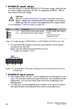
Figure 16: Connecting the supply voltage at the 6-pin terminal block
1 – DC voltage, voltage range: 9.6 V DC to 60 V DC
2 – AC voltage, voltage range: 18 V AC to 30 V AC
Note:
With non-redundant supply of the mains voltage, the device reports
a power failure. You can avoid this message by changing the
configuration in the management, or, with power supply units of the same
type, by feeding the supply voltage in via both inputs.
Signal contact for RS20/RS30/RS40
The signal contact (“FAULT”, for pin assignment of terminal block, see
figure 16
) monitors the functioning of the device, thus enabling remote
diagnostics. You can specify the type of function monitoring in the
Management.
You can also use the graphical user interface of the switch to switch
the signal contact manually and thus control external devices.
The potential-free signal contact (relay contact, closed circuit) reports
through a break in contact:
The detected inoperability of at least one of the two voltage supplies
(voltage supply 1 or 2 is below the threshold value).
The device is not operational.
The failure of the connection on at least one port.
The report of the link status can be masked by the Management for
each port. In the delivery state, is deactivated.
Failure of the ring redundancy reserve.
Errors detected during the self-diagnostic test.
Incorrect configuration of the HIPER-Ring or ring coupling.
FAULT
G
G
+24V(P1)
0V 0V
+24V(P2)
FAULT
+24V(P1)
0V 0V
+24V(P2)
+
-
-
+
1
1
2
2
Summary of Contents for Hirschmann RPS90/48V HV
Page 66: ......


