background image

54

Installation RS20/22/30/32/40

Release 03 06/2013

2.4

Maintenance

When designing this device, Hirschmann was largely able to forego using 
parts that are subject to wear and tear. The parts subject to wear are 
designed to last longer than the lifetime of the product when it is operated 
properly. Operate this device according to the specifications (see 

“Technical data”

).

Relays are subject to natural wear. This wear depends on the frequency 
of the switching operations. Check the resistance of the closed relay 
contacts and the switching function depending on the frequency of the 
switching operations.

Hirschmann is continually working to improve and develop our software. 
You should regularly check whether there is a new version of the software 
that provides you with additional benefits. You will find software 
information and downloads on the product pages of the Hirschmann 
website.

Depending on the degree of pollution in the operating environment, check 
at regular intervals that the ventilation slots in the device are not 
obstructed.

Note: 

You will find information about the complaints and returns procedures 

in the Internet under 

http://www.beldensolutions.com/en/Service/Repairs/index.phtml

.

Summary of Contents for Hirschmann RPS90/48V HV

Page 1: ...24 USB P Stand by FAULT RM ON RS20 LS DA RM 24V P1 0V 0V FAULT 24V P2 Stand by Aufkleber MAC Adresse IP ADDRESS 2 LS DA 1 3 5 7 4 6 8 V 24 USB P Stand by FAULT RM ON RS20 RM Stand by Aufkleber MAC Adresse IP ADDRESS V 24 USB P Stand by FAULT RM ON LS 1 DA LS 2 DA LS 3 DA LS 4 DA RS20 0800 RS20 2400 RS20 0400 RM Stand by Aufkleber MAC Adresse IP ADDRESS V 24 USB P Stand by FAULT RM ON RM Stand by A...

Page 2: ...es described here are binding only if they have been expressly agreed when the contract was made This document was produced by Hirschmann Automation and Control GmbH according to the best of the company s knowledge Hirschmann reserves the right to change the contents of this document without prior notice Hirschmann can give no guarantee in respect of the correctness or accuracy of the information ...

Page 3: ...1 2 2 PoE power units 31 2 Assembly and start up 32 2 1 Installing the device 32 2 1 1 Unpacking and checking 32 2 1 2 Installing the SFP transceivers optional 33 2 1 3 Insert data in label area 33 2 1 4 Adjust DIP switch settings 34 2 1 5 RS20 RS30 RS40 supply voltage and signal contact 34 2 1 6 RS22 RS32 supply voltage and signal contact 36 2 1 7 Installing the device on the DIN rail grounding 4...

Page 4: ...ply voltage that fulfills the requirements of the National Electrical Code Table 11 b If the voltage is being supplied redundantly two different voltage sources the combined supply voltages must fulfill the requirements of the National Electrical Code Table 11 b Relevant for North America For use in class 2 circuits Use 60 75 C 140 167 F or 75 C 167 F copper Cu wire only Relevant for North America...

Page 5: ...supply voltage as described in the data plate of your device PoE power supply unit RPS90 48V LV 18 V DC to 60 V DC PoE power supply unit RPS90 48V HV 48 V DC to 320 V DC or 90 V AC to 265 V AC If the neutral conductor or the negative terminal of the supply voltage is not grounded If you are using a DC voltage greater than 125 V DC for the supply voltage install a suitable input fuse For RPS90 48V ...

Page 6: ... LOCATIONS OR NON HAZARDOUS LOCATIONS ONLY WARNING EXPLOSION HAZARD SUBSTITUTION OF ANY COMPONENTS MAY IMPAIR SUITABLE FOR CLASS I DIVISION 2 WARNING EXPLOSION HAZARD DO NOT DISCONNECT EQUIPMENT WHILE THE CIRCUIT IS LIVE OR UNLESS THE AREA IS KNOWN TO BE FREE OF IGNITABLE CONCENTRATIONS The USB connector is for temporary connection only Do not use connect or disconnect unless area is known to be n...

Page 7: ... SUITABILITY FOR HAZARDOUS LOCATIONS OR EXPLOSIVE ATMOSPHERES WARNING EXPLOSION HAZARD DO NOT DISCONNECT EQUIPMENT UNLESS POWER HAS BEEN SWITCHED OFF OR THE AREA IS KNOWN TO BE NON HAZARDOUS DO NOT OPEN WHEN ENERGIZED CONTROL DRAWING for RS20 RS22 RS30 RS32 and RS40 Family Size A4 Document No 000157671DNR Rev 0 Date 2011 09 21 Sheet 1 of 1 NON HAZARDOUS LOCATION USB Port for Auto Configuration Ada...

Page 8: ...0 C for S types item 14 of nomenclature breakdown or T4 40 C Ta 70 C for T or E types item 14 of nomenclature breakdown Ambient rating and temperature code for RS22 and RS32 types T4 40 C Ta 50 C for T or E types item 14 of nomenclature breakdown or T4 0 C Ta 50 C for S Typen item 14 of nomenclature breakdown Ambient rating and temperature code for RS40 types T3 40 C Ta 70 C for T or E types item ...

Page 9: ...all remain disconnected Housing Only technicians authorized by the manufacturer are permitted to open the housing The housing is grounded via the separate ground screw on the bottom left of the front panel WARNING ELECTRIC SHOCK Never insert sharp objects small screwdrivers wires etc into the inside of the device Never insert sharp objects small screwdrivers wires etc into the connection terminals...

Page 10: ... device in an environment within the pollution degree specified in the technical data Qualification requirements for personnel Qualified personnel as understood in this manual and the warning signs are persons who are familiar with the setup assembly startup and operation of this product and are appropriately qualified for their job This includes for example those persons who have been trained or ...

Page 11: ... by personnel trained for this purpose Note LED or LASER components in compliance with IEC 60825 1 2007 CLASS 1 LASER PRODUCT CLASS 1 LED PRODUCT National and international safety regulations Make sure that the electrical installation meets local or nationally applicable safety regulations E marking The labeled devices comply with the regulations contained in the following European directive s RPS...

Page 12: ...rator may be required to take appropriate measures Note The assembly guidelines provided in these instructions must be strictly adhered to in order to observe the EMC threshold values FCC note This device complies with part 15 of the FCC rules Operation is subject to the following two conditions 1 this device may not cause harmful interference 2 this device must accept any interference received in...

Page 13: ...n RS20 22 30 32 40 Release 03 06 2013 13 Recycling note After usage this device must be disposed of properly as electronic waste in accordance with the current disposal regulations of your county state and country ...

Page 14: ...dancy Configuration user manual Reference manual for the graphical user interface Command Line Interface user manual The Industrial HiVision Network Management Software provides you with additional options for smooth configuration and monitoring Simultaneous configuration of multiple devices Graphical user interface with network layout Auto topology discovery Event log Event handling Client server...

Page 15: ...Ethernet networks that conform to the IEEE 802 3 standard The devices work without a fan The voltage is supplied redundantly The following installation options are available simply snapping them onto a DIN rail mounting them on a wall only RS22 RS32 Depending on the device variant you can choose various media to connect terminal devices and other infrastructure components twisted pair cable multim...

Page 16: ...gments The table below shows three port categories for each product variant uplink ports PoE ports and other ports The table also shows for each product category the number of ports you can select and the type of ports In the column for the port type the abbreviations F O optical fiber and TP twisted pair indicate the media type while the abbreviations DSC ST SFP and RJ45 indicate the socket type ...

Page 17: ...TP RJ45 4 10 100 Mbit s TP RJ45 RS40 4 Ports 1 to 4 4 combo ports 100 1000 Mbit s F O SFP 10 100 1000 Mbit s TP RJ45 5 10 100 1000 Mbit s TP RJ45 Item Characteristic Ident Ident 2 a Property 1 to 4 Product RS20 Rail Switch without gigabit ports RS30 Rail Switch with gigabit ports RS22 Rail Switch without gigabit ports with PoEb c RS32 Rail Switch with gigabit ports with PoEd e 5 hyphen 6 to 7 Numb...

Page 18: ...01 UL 1604 GL Railway along track Sub Station Hazardous Location ATEX 17 Software variant E Enhanced P Professional a For device variants with two uplink ports you use the Ident column for items 10 11 and for items 12 13 For device variants with three uplink ports you use the Ident 2 column for items 10 11 and the Ident column for items 12 13 For device variants with four uplink ports you use the ...

Page 19: ... 508 ATEX or ISA 12 12 01 certification the maximum operating temperature for the extended T temperature range for PoE capable devices RS22 RS32 50 C w Not when using GG or G2 transceivers x In combination with 2nd uplink port ZZ and 1st uplink port OO y Not for PoE capable devices RS22 RS32 z For PoE capable devices RS22 RS32 aa Without railway certification EN 50155 Train RS20 RS20 Rail Switch w...

Page 20: ... 3 Item Characteristic Ident Property 1 to 4 Product RS40 Rail Switch with gigabit ports 5 hyphen 6 and 7 Number of 10 100 Mbit s ports 00 0 10 100 Mbit s Ethernet 8 and 9 Number of 1000 Mbit s ports 09 9 1000 Mbit s Ethernet 10 and 11 1st 2nd uplink port CC 2 combo port multirate SFP slot 100 1000 Mbit s alternatively twisted pair RJ45 socket 10 100 1000 Mbit s 12 and 13 3rd 4th uplink port CC 2 ...

Page 21: ...00 1000 Mbit s CC CC Port 3 4 combo port SFP slot 100 1000 Mbit s alternatively RJ45 connector 10 100 1000 Mbit s E E Temperature range extended 40 C to 70 C with conformal coating D D Voltage range 9 6 V DC to 60 V DC or 18 V AC to 30 V AC A A Certifications CE UL 508 ISA 12 12 01 UL 1604 P P Software variant Professional Table 6 Example of RS40 with 4 uplink ports RS40 0009CCCCEDAP RS20 RM Stand...

Page 22: ...100 Mbit s ports RS20 0800 1 to 9 see figure 1 RS20 LS DA RM 24V P1 0V 0V FAULT 24V P2 Stand by Aufkleber MAC Adresse IP ADDRESS 2 LS DA 1 3 5 7 4 6 8 V 24 USB P Stand by FAULT RM ON 1 2 3 4 5 6 7 8 9 7 RS20 0800M2M2 D RS20 RM 24V P1 0V 0V FAULT 24V P2 Stand by Aufkleber MAC Adresse IP ADDRESS 1 3 5 7 2 4 6 8 V 24 USB P Stand by FAULT RM ON RS20 0800T1T1 D RS20 RM 24V P1 0V 0V FAULT 24V P2 Stand b...

Page 23: ...RM 24V P1 0V 0V FAULT 24V P2 Stand by Aufkleber MAC Adresse IP ADDRESS 1 3 5 7 2 4 6 8 9 11 13 15 10 12 14 16 V 24 USB P Stand by FAULT RM ON RS20 1600T1T1 D RS20 1600M2T1 D RS20 LS DA RM 24V P1 0V 0V FAULT 24V P2 Stand by Aufkleber MAC Adresse IP ADDRESS 3 5 7 9 11 13 15 17 2 LS DA 1 4 6 8 10 12 14 16 18 19 21 23 20 22 24 V 24 USB P Stand by FAULT RM ON RS20 RM 24V P1 0V 0V FAULT 24V P2 Stand by ...

Page 24: ...C 100 Mbit s UU Singlemode FX ST 100 Mbit s LL Singlemode Longhaul FX DSC 100 Mbit s GG Singlemode Longhaul FX DSC 100 Mbit s 200 km 10 IP address field RS20 24V P1 0V 0V FAULT 24V P2 4 6 8 10 12 14 16 18 5 7 9 11 13 15 17 19 20 22 24 21 23 25 RS20 24V P1 0V 0V FAULT 24V P2 4 6 8 10 5 7 9 11 12 14 16 13 15 17 RS20 24V P1 0V 0V FAULT 24V P2 4 6 8 5 7 9 LS DA 2 LS DA 1 LS DA 3 LS DA 2 LS DA 1 LS DA ...

Page 25: ...ons T1 Twisted pair T X RJ45 10 100 1000 Mbit s O6 SX LX SFP slot 1000 Mbit s 8 MAC address field 9 IP address field RS30 RM 24V P1 0V 0V FAULT 24V P2 Stand by Aufkleber MAC Adresse IP ADDRESS 3 5 7 9 4 6 8 10 V 24 USB P Stand by FAULT RM ON DA 2 LS DA 1 LS RS30 RM 24V P1 0V 0V FAULT 24V P2 Stand by Aufkleber MAC Adresse IP ADDRESS LS DA 1 V 24 USB P Stand by FAULT RM ON DA 2 LS 3 5 7 9 4 6 8 10 R...

Page 26: ... by Aufkleber MAC Adresse IP ADDRESS V 24 USB P Stand by FAULT RM ON 3 5 7 9 4 6 8 10 11 13 15 17 12 14 16 18 LS DA 1 LS DA 2 RS30 1602T1T1 D RS30 1602O6O6 D RS30 1602O6T1 D 1 2 3 4 5 6 6 6 7 8 9 7 RS30 RM 24V P1 0V 0V FAULT 24V P2 Stand by Aufkleber MAC Adresse IP ADDRESS 3 5 7 9 11 13 15 17 4 6 8 10 12 14 16 18 19 21 23 25 20 22 24 26 V 24 USB P Stand by FAULT RM ON 2 DA LS 1 DA LS RS30 RM 24V P...

Page 27: ...S30 24V P1 0V 0V FAULT 24V P2 5 7 9 11 6 8 10 12 13 15 17 14 16 18 RS30 24V P1 0V 0V FAULT 24V P2 5 7 9 6 8 10 LS DA 1 LS DA 2 LS DA 3 LS DA 4 LS DA 1 LS DA 2 LS DA 3 LS DA 4 LS DA 1 LS DA 2 LS DA 3 LS DA 4 RM Stand by Aufkleber MAC Adresse IP ADDRESS V 24 USB P Stand by FAULT RM ON RM Stand by Aufkleber MAC Adresse IP ADDRESS V 24 USB P Stand by FAULT RM ON RM Stand by Aufkleber MAC Adresse IP AD...

Page 28: ... Alternatively T X RJ45 connections 10 100 1000 Mbit s 7 ports in compliance with 10 100 1000BASE T X RJ45 connections RS40 24V P1 0V 0V FAULT 24V P2 1 3 5 7 2 4 6 8 1 2 3 4 RM Stand by Aufkleber MAC Adresse IP ADDRESS V 24 USB P Stand by FAULT RM ON 9 1 2 3 4 5 6 7 7 6 8 9 RS40 0009CCCCSD RS40 24V P1 0V 0V FAULT 24V P2 1 3 5 7 2 4 6 8 1 2 3 4 RM Stand by Aufkleber MAC Adresse IP ADDRESS V 24 USB ...

Page 29: ...E example RS22 1700MMM2 P 1 to 5 and 7 to 9 see figure 5 6 ports in compliance with 10 100BASE T X RJ45 connections the PoE capable ports 14 to 17 are indicated accordingly RS22 RM Stand by Aufkleber MAC Adresse IP ADDRESS V 24 USB P Stand by FAULT RM ON 1 2 3 4 5 6 6 6 LS DA 2 LS DA 1 LS DA 3 7 9 8 10 9 4 6 8 10 5 7 9 11 12 14 16 13 15 17 RS22 1700MMM2 P FAULT 48V P1 0V 0V 48V P2 ...

Page 30: ...s provide four 10BASE T 100BASE TX ports RJ45 sockets for connecting network segments or PoE terminal devices PD Powered Device for all IEEE802 3af classes up to a maximum power output of 15 4 W The four PoE capable ports are the four bottom ports on the right side of the device see figures in section Number of ports and media for devices with PoE on page 29 The PoE ports are indicated in red on t...

Page 31: ...DC Power output at up to 60 C 90 W Power output at 60 C to 70 C 60 W RPS90 48V HV High voltage PoE power unit Input voltage range 60 V DC to 250 V DC or 110 V AC to 230 V AC You can choose between a DC or AC voltage connection Power output at up to 60 C 90 W Power output at 60 C to 70 C 60 W The output voltage can be set in the range from 48 V DC to 54 V DC The default setting for the output volta...

Page 32: ...djust DIP switch settings Connect PoE power unit optional Connect the terminal block for voltage supply and signal contact and connect the supply voltage Install the device on the DIN rail grounding Install the terminal block start up procedure Connecting the data lines 2 1 Installing the device 2 1 1 Unpacking and checking Check whether the contents of the package are complete Scope of delivery o...

Page 33: ...igure 13 F O SFP transceiver Note Only use Hirschmann SFP transceivers See Accessories on page 63 2 1 3 Insert data in label area The information field for the IP address on the front of the device helps you to structure your network installation clearly Figure 14 Label area for IP address of device 1 IP address of device label area 2 MAC address of device label RS20 LS DA RM 24V P1 0V 0V FAULT 24...

Page 34: ...load capability of the signal contact is not exceeded Technical data on page 56 Supply voltage for RS20 RS30 RS40 Redundant power supplies can be used Both inputs are uncoupled There is no distributed load With redundant supply the power supply unit supplies the device only with the higher output voltage The supply voltage is electrically isolated from the housing See Insulation voltage in section...

Page 35: ...te diagnostics You can specify the type of function monitoring in the Management You can also use the graphical user interface of the switch to switch the signal contact manually and thus control external devices The potential free signal contact relay contact closed circuit reports through a break in contact The detected inoperability of at least one of the two voltage supplies voltage supply 1 o...

Page 36: ... world 2 250 V DC for 1 min Output power 100 W Current limitation 5 A The power supply unit and the devices with PoE ports form a limited power source according to IEC 60950 1 The external PoE power supply unit must be able to provide the power for the connected PDs Power Devices and for the Switch Note The RS22 RS32 devices fulfill the technical data and the certifications when using the RPS90 48...

Page 37: ...ons If the neutral conductor or the minus terminal of the supply voltage is not grounded install a suitable fuse in the input line For supply voltages 125 V DC Install a suitable external fuse in the supply voltage input line of the plus terminal Use a supply cable with a maximum length of 2 meters to the power unit Figure Pin Assignment Voltage range 1 Protective conductor High voltage input volt...

Page 38: ...uirements are met Supply line length 0 5 m Figure 17 Connecting the PoE supply voltage at the 6 pin terminal block of device RS22 RS32 RS22 RS32 signal contact The signal contact FAULT for pin assignment of terminal block see figure 16 monitors the functioning of the device thus enabling remote diagnostics You can specify the type of function monitoring in the Management You can also use the graph...

Page 39: ...the connection on at least one port The report of the link status can be masked by the Management for each port In the delivery state is deactivated Failure of the ring redundancy reserve Errors detected during the self diagnostic test Incorrect configuration of the HIPER Ring or ring coupling The following condition is also reported in RM mode Ring redundancy reserve is available On delivery ther...

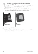
Page 40: ...m onto the DIN rail Mount the device on a 35 mm DIN rail in accordance with DIN EN 60175 Attach the upper snap in guide of the device into the DIN rail and press the device down against the DIN rail until it snaps into place Figure 18 Mounting on the DIN rail Note The shield ground wire of the twisted pair lines is connected to the front panel as a conductor RS20 RS30 RS40 RS22 RS32 ...

Page 41: ...il on DIN rail Mount one mounting kit on each side of your RS30 0802 device but at least one mounting kit on one side of the RS30 0802 device If possible position one side of the RS30 0802 device on a wall or in a similarly stable way If you are positioning multiple RS30 0802 devices side by side mount the row of devices in the way described for a single device Mount a standard DIN rail stopper on...

Page 42: ...ll using the wall mounting plate supplied Accessories on page 63 Figure 20 Mounting the RS22 RS32 devices on the wall Mount the device on the wall plate as shown in the illustration Insert the upper snap in guide of the device into the rail and press it down against the rail until it snaps into place Fasten the wall plate see on page 63 Accessories on a level wall surface using four screws ...

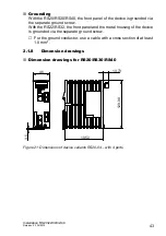
Page 43: ...und screw With the RS22 RS32 the front panel and the metal housing of the device is grounded via the separate ground screw For the ground conductor use a cable with a cross section of at least 1 0 mm 2 1 8 Dimension drawings Dimension drawings for RS20 RS30 RS40 Figure 21 Dimensions of device variants RS20 04 with 4 ports 46 129 08 105 3 3 5 13 73 ...

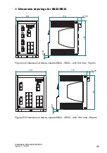
Page 44: ... RS20 22 30 32 40 Release 03 06 2013 Figure 22 Dimensions of device variants RS20 RS30 RS40 with 8 to max 10 ports Figure 23 Dimensions of device variants RS20 RS30 RS40 with 16 to max 26 ports 130 105 3 13 73 3 5 72 ...

Page 45: ... 03 06 2013 45 Dimension drawings for RS22 RS32 Figure 24 Dimensions of device variants RS22 RS32 with 8 to max 10 ports Figure 25 Dimensions of device variants RS22 RS32 with 16 to max 26 ports 90 115 11 56 9 03 137 120 115 11 56 9 03 137 ...

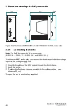
Page 46: ...E devices with 16 or more ports RS22 16 RS22 17 RS22 24 and RS22 25 To adhere to EMC conformity you connect the ferrite supplied to the voltage input via the voltage supply line Insert both cables of the 48V output through the ferrite twice Lock the ferrite Position the ferrite as close as possible to the voltage output max distance 50 cm To open the ferrite use the key supplied 60 115 7 05 8 93 1...

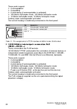
Page 47: ...Connecting the data lines You can connect terminal devices and other segments on the ports of the device via twisted pair cables or F O cables Install the data lines according to your requirements 10 100 Mbit s twisted pair connection These connections are RJ45 sockets 10 100 Mbit s TP ports enable the connection of terminal devices or independent network segments according to the IEEE 802 3 10BAS...

Page 48: ...k segments according to the IEEE 802 3 10BASE T 100BASE TX and IEEE 802 3af Power over Ethernet standards These ports support Autonegotiation Autopolarity Autocrossing if autonegotiation is activated 100 Mbit s half duplex mode 100 Mbit s full duplex mode 10 Mbit s half duplex mode 10 Mbit s full duplex mode Power over Ethernet PoE at the last four ports of the device Delivery state autonegotiatio...

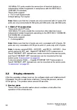
Page 49: ... Delivery state autonegotiation activated The socket housing is electrically connected to the front panel The pin assignment corresponds to MDI X 100 Mbit s F O connection In device variants RS20 and RS22 these ports are DSC connectors or ST connectors In device variants RS30 RS32 and RS40 these ports are SFP slots Figure Pin Function PoE 1 RD Receive Data V 2 RD Receive Data V 3 TD Transmit Data ...

Page 50: ... LH ports are only connected with LH ports SX ports are only connected with SX ports and LX ports only with LX ports Note In device variants RS30 02OOZZ and RS32 02OOZZ four uplink ports with SFP slot Gigabit ETHERNET SFP transceivers or Fast ETHERNET SFP transceivers can be mounted at the two top ports and Fast ETHERNET SFP transceivers can be mounted at the two bottom ports Accessories on page 6...

Page 51: ...active on the FAULT signal contact then the detected error display is independent of the setting of the signal contact Glowing red The signal contact is open i e it is reporting a detected error Not glowing The signal contact is closed i e it is not reporting a detected error RM Ring Manager green yellow LED Glowing green RM function active redundant port disabled Glowing yellow RM function active...

Page 52: ...24 data rate 9 600 Baud Ring redundancy disabled Ethernet ports link status is not evaluated signal contact Optical 100 Mbit s ports 100 Mbit s full duplex All other ports autonegotiation Ring Manager disabled DIP switch RM and stand by ON Stand by coupling disabled DIP switch RM and stand by ON Port 4 control port port 3 coupling port for red Ring coupling Rapid Spanning Tree enabled USB interfac...

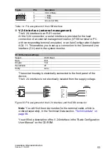
Page 53: ...e front panel of the device The V 24 interface is not electrically isolated from the supply voltage Figure 30 Pin assignment of the V 24 interface and the DB9 connector Note You will find the order number for the terminal cable which is ordered separately in the Technical Data section Technical data on page 56 You will find a description of the V 24 interface in the Basic Configuration User Manual...

Page 54: ...losed relay contacts and the switching function depending on the frequency of the switching operations Hirschmann is continually working to improve and develop our software You should regularly check whether there is a new version of the software that provides you with additional benefits You will find software information and downloads on the product pages of the Hirschmann website Depending on t...

Page 55: ...king slide pull it without tipping the screwdriver downwards and lift the device upwards Removing the device from the wall mounting plate To remove the device from the rail of the wall plate press the device downwards and pull it from the rail below Removing the SFP transceivers Pull the module out of the socket by means of the opened lock Close the module with the protective cap RS20 RS30 RS40 RS...

Page 56: ...400 RS20 08 RS20 09 RS30 0802 RS20 16 RS20 17 RS30 1602 RS20 24 RS20 25 RS30 2402 RS40 0009CCCCS RS40 0009CCCCE RS40 0009CCCCT 400 g 410 g 600 g 650 g 530 g 600 g RS22 08 RS22 09 RS32 0802 RS22 16 RS22 17 RS32 1602 RS22 24 RS22 25 RS32 2402 820 g 1150 g 1200 g RPS 90 48V LV PoE power unit RPS 90 48V HV PoE power unit 770 g 740 g Power supply Operating voltage RS20 RS30 RS40 Rated voltage range DC ...

Page 57: ... voltage DC 24 V 48 V Voltage range DC 18 60 V incl max tolerances Current consumption at 24 V DC Current consumption at 48 V DC 4 20 A 2 10 A Connection type 2 pin terminal block Output voltage 48 54 V DC variable default value 48 V DC Power output At up to 60 C 90 W At 60 C to 70 C 60 W Power failure bypass 10 ms Overload current protection at input Non replaceable fuse Insulation voltage betwee...

Page 58: ... UL 508 ATEX or ISA 12 12 01 certification the maximum operating temperature for the standard S temperature range for PoE capable devices RS22 RS32 is 50 C c With a UL 508 ATEX or ISA 12 12 01 certification the maximum operating temperature for the extended E and T temperature range for PoE capable devices RS22 RS32 is 50 C EMC compliance IEC EN 61000 6 2 2005 EMI TYPE tests test acc to A a B a H ...

Page 59: ...uct code M SFP Wave length Fiber System attenuatio n Example for F O line length a a including 3 dB system reserve when compliance with the fiber data is observed Fiber attenuatio n BLPb dispersion b The bandwidth length product cannot be used to calculate the expansion SX LC MM 850 nm 50 125 µm 0 7 5 dB 0 550 m 3 0 dB km 400 MHz km SX LC MM 850 nm 62 5 125 µm 0 7 5 dB 0 275 m 3 2 dB km 200 MHz km...

Page 60: ...nuation BLP dispersion MM LC MM 1310 nm 50 125 µm 0 8 dB 0 5 km 1 0 dB km 800 MHz km MM LC MM 1310 nm 62 5 125 µm 0 11 dB 0 4 km 1 0 dB km 500 MHz km SM LC SM 1310 nm 9 125 µm 0 13 dB 0 25 km 0 4 dB km 3 5 ps nm km SM LC SM 1310 nm 9 125 µm 10 29 dB 25 65 km 0 4 dB km 3 5 ps nm km LH LC SM 1550 nm 9 125 µm 10 29 dB 47 104 km 0 25 dB km 19 ps nm km LH LC SM 1550 nm 9 125 µm 10 29 dB 55 140 km 0 18 ...

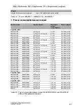
Page 61: ...2 2400 1xFX port 1xTX port 13 3 W 45 4 Btu IT h RS20 2400 RS22 2400 2xFX port 14 5 W 52 9 Btu IT h RS30 0802 RS32 0802 2xTX port 8 9 W 30 4 Btu IT h RS30 0802 RS32 0802 1xFX port 1xTX port 8 6 W 29 4 Btu IT h RS30 0802 RS32 0802 2xFX port 8 3 W 28 4 Btu IT h RS30 1602 RS32 1602 2xTX port 13 0 W 44 4 Btu IT h RS30 1602 RS32 1602 1xFX port 1xTX port 12 7 W 43 4 Btu IT h RS30 1602 RS32 1602 2xFX port...

Page 62: ...Btu IT h RS32 0802 2xTX port 74 5 W 44 1 Btu IT h RS32 0802 1xFX port 1xTX port 74 2 W 43 1 Btu IT h RS32 0802 2xFX port 73 9 W 42 1 Btu IT h RS32 1602 2xTX port 78 6 W 58 1 Btu IT h RS32 1602 1xFX port 1xTX port 78 3 W 57 1 Btu IT h RS32 1602 2xFX port 78 0 W 56 1 Btu IT h RS32 2402 2xTX port 81 3 W 67 3 Btu IT h RS32 2402 1xFX port 1xTX port 81 0 W 66 3 Btu IT h RS32 2402 2xFX port 80 7 W 65 3 B...

Page 63: ...MM LC EEC 943 945 001 M FAST SFP SM LC 943 866 001 M FAST SFP SM LC EEC 943 946 001 M FAST SFP SM LC 943 867 001 M FAST SFP SM LC EEC 943 947 001 M FAST SFP LH LC 943 868 001 M FAST SFP LH LC EEC 943 948 001 Special accessories for the device variants RS22 RS32 Order number RSR wall mounting plate width 120 mm 943 971 001 RSR wall mounting plate width 90 mm 943 971 002 RSR wall mounting plate widt...

Page 64: ...Part 6 2 Generic standards Immunity for industrial environments EN 61131 2 Programmable controllers Part 2 Equipment requirements and tests FCC 47 CFR Part 15 Code of Federal Regulations Germanischer Lloyd Rules for Classification and Construction VI 7 2 GL EN 60950 1 Information technology equipment Safety Part 1 General requirements IEC EN 61850 3 Communication networks and systems in substation...

Page 65: ...9860 E mail inet ap belden com Hirschmann Competence Center The Hirschmann Competence Center is ahead of its competitors Consulting incorporates comprehensive technical advice from system evaluation through network planning to project planning Training offers you an introduction to the basics product briefing and user training with certification The current technology and product training courses ...

Page 66: ......
Reviews: