2
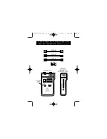
1. Plug the first end of the cable into the modular jack on
the master unit marked with “
▲
” (plug the RJ45/BNC
adapter on first for the coax cable testing), then plug the
second end of the cable at the remote location into the
modular jack on the remote terminator. Then repeat the
instructions from section “A-2”, except compare the LEDs
on the remote terminator to the LEDs on the master unit.
If the remote end of the cable is connected to a faceplate
or patch panel, you will need to use the included
RJ45/RJ45 or RJ45/BNC adapters to connect the cable to
the remote terminator.
C. To do the Remote Test (F4F314-T only)
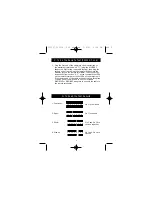
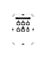
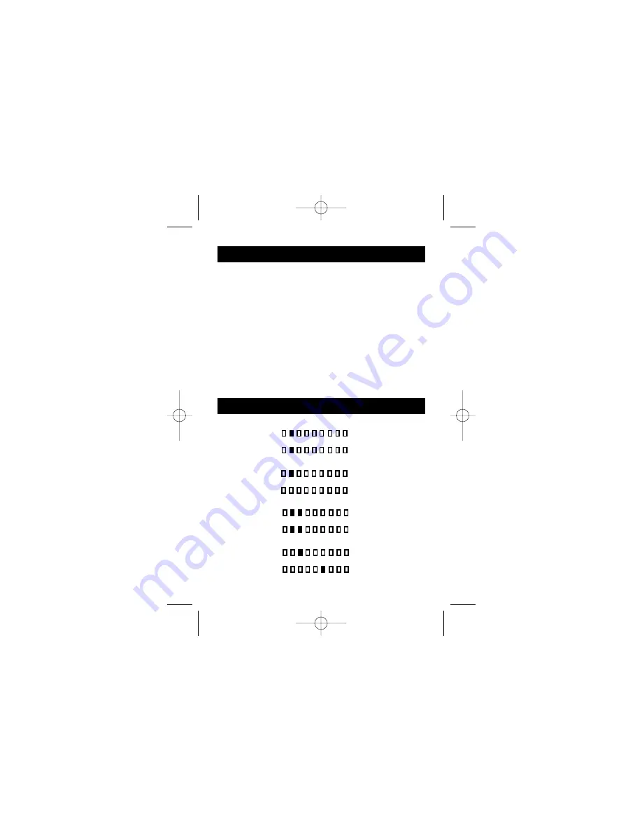
D. To Read the Test Results
1 2 3
G
8
7
6
5
4
1 2 3
G
8
7
6
5
4
1 2 3
G
8
7
6
5
4
1 2 3
G
8
7
6
5
4
1. Continuity:
2. Open:
3. Short:
4. Miswire:
Pin 2 is continued
Pin 2 is opened
Pin 2 and Pin 3 are
shorted together
Pin 3 and Pin 6 are
crossed
P73237_F5F314_-T_US_man.qxd 2/9/01 3:24 PM Page 2


