

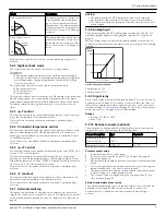

Mode
Description
Proportional pressure
2
Hset
Hset
The pump pressure is continuous-
ly increased/decreased depend-
ing on the increased/decreased
flow demand. The maximum head
of the pump can be set via user in-
terface. See section 6.1.2 Change
set point.
Fixed speed control
Max
min
Speed
setpoint
The pump maintains a fixed speed
at any flow demand. The speed of
the pump can be set via user inter-
face. See section 6.1.2 Change set
point.
All the above control modes can be combined with the night mode
function.
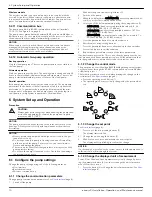
5.2.2 Night set back mode
The night set back mode cannot be used in cooling systems.
Prerequisite
• The pump is installed between boiler outlet and system supply.
• The night set back feature is initiated when the pump recognizes a
water temperature change brought about by the boiler or high
level control system.
The night set back mode is active only in combination with:
• Proportional pressure
• Constant pressure
• Constant speed
This function reduces power consumption of the pump to the minimum
when heating system is not running. An algorithm detects the water
temperature change and automatically adjusts the speed of the pump.
The pump returns to the original set point as soon as the system re-
starts.
5.2.3 ∆p-T control
This function adjusts the nominal differential pressure set point accord-
ing to the temperature of the pumped media.
For details refer to advanced functions manual on www.bellgos-
sett.com
5.2.4 T-Constant temperature control
This functional mode changes the speed of the pump in order to main-
tain a constant temperature of the pumped media. It is suitable for
heating systems with fixed system characteristics, for example Domes-
tic Hot Water Systems.
For details, refer to the advanced functions manual on www.bellgos-
sett.com
5.2.5 ∆p-∆T control
This function requires the external temperature probe type KTY83 (see
section 5.2.10 of this manual).
This function adjusts the nominal differential pressure set point de-
pending on the differential temperature of the pumped media. An ex-
ternal temperature sensor Type: KTY83 is required for this functionality
(see section 5.2.10 of this manual for details).
For details, refer to the advanced functions manual on www.bellgos-
sett.com
5.2.6 ∆T constant
This function alters the speed of the pump in order to maintain a con-
stant differential temperature of the pumped media.
For details, refer to the advanced functions manual on www.bellgos-
sett.com
5.2.7 External start/stop
The pump can be started or stopped via an external dry contact or a
relay that is connected to terminals 11 and 12. The pump unit is provid-
ed by default, with the terminals 11 and 12 jumpered. See Figure 4 on
page 8.
NOTICE:
• The pump provides 5 VDC through the start / stop terminals.
• No external voltage must be provided to start / stop terminals.
• The cables connected to terminals 11 and 12 shall not exceed 65
feet in length.
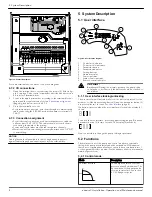
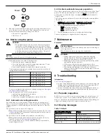
5.2.8 Analog Input
The pump integrates a 0-10 V analog input at terminals 7 and 8. See
terminal diagram figures for changing the setpoint. See Figure 4 on
page 8.
When a voltage input is detected, the pump switches to fixed speed
control mode automatically and starts to run according to the following
diagram:
Vin[V]
Speed
[rpm]
Vset
10
1.5
1.2
min
Max
Setpoint
Figure 6: Voltage input detected
Pump stops at 1.2 V
Pump restarts at 1.5 V
5.2.9 Signal relay
A dry contact relay is provided at terminals 4 and 5. See connection di-
agram, figure 4 on page 8, for location. If there is a fault, the relay con-
tact closes to display a red status light and the error code on the user
interface display. See
User interface
(page 8). The relay contact closure
can also be used to energize a remote fault display.
Ratings
• Voltage: 115/208 – 230/1
• Imax < 2 A
5.2.10 External sensors (optional)
The pump can be equipped with a differential pressure sensor and a
temperature sensor according to the following table:
Sensor description
Type
Terminals
Differential pressure
sensor 4-20mA
15 PSI
30 PSI
9 - 10
Temperature sensor
KTY83/121
13 - 14
Pressure sensor setup
1.
Install pressure sensor on the pipe
2.
Connect wires at terminals 9 and 10. See Figure 4 on page 8.
3.
Power the pump on.
4.
Upon startup, the pump detects the sensor and displays the setup
menu.
5.
Select the right sensor model and confirm the selection using the
parameter button (3). See
User interface
(page 8).
6.
The pump will run through the startup sequence and automatical-
ly start working in constant pressure mode.
7.
The setpoint can be changed using the settings button (5). See
User interface
(page 8).
External temperature sensor setup
The external temperature sensor setup and related control modes are
available only through RS-485 or wireless module connection.
For details refer to advanced functions manual on www.bellgos-
sett.com
5 System Description
ecocirc XL Installation, Operation, and Maintenance manual
9


