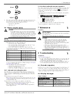
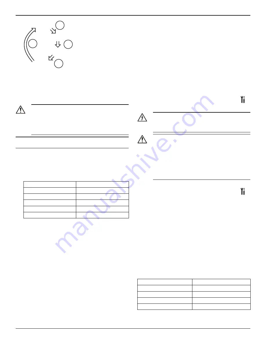
background image

Power

Speed

Head

Flow

Parameter

button

Parameter

button

Parameter

button

Parameter

button

2.

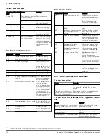
When flow and head are displayed, by pressing the button (3) for

more than one second at each of these parameters, the unit of

measurement automatically changes as below:

• Flow: m3/h 

↔ 

gpm (US)

• Head: m 

↔ 

ft

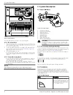
6.2  Start or stop the pump

CAUTION:

• The pump must not run dry as this can result in prema-

ture failure of the bearings in a very short time. Fill and

vent the system correctly before first start-up. The pump

rotor chamber will be vented after the pump is powered

on with an automatic air venting procedure. "deg" will

be displayed indicating degassing process.

NOTICE:

The system cannot be vented through the pump.

• Start the pump in one of the following ways:

• Switch on power to supply the pump.

• Close the start/stop contact by jumpering terminals 11 and

12 or through a remote dry contact..

• Send start command through the communication bus.

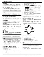
The pump starts pumping in constant pressure mode with the fol-

lowing default set points:

7.5 ft

15–XX (Max head 15 ft)

10 ft

20–XX (Max head 20 ft)

18 ft

36–XX (Max head 36 ft)

20 ft

40–XX (Max head 40 ft)

27.5 ft

55–XX (Max head 55 ft)

32.5 ft

65–XX (Max head 65 ft)

For more information about how to change setting, see 

Configure

the pump settings

 (page 10).

• Stop the pump in one of the following ways:

• Switch off power supply to the pump.

• Open the start/stop contact.

• Send stop command through the communication bus.

6.2.1  Automatic air venting procedure

At each power-on of the pump unit, an automatic air venting proce-

dure is executed. During this phase, the user interface displays "deg"

(degassing) and a count-down begins until the completion of the pro-

cedure.
The procedure can be recalled or skipped:

• Manually by pressing simultaneously the two buttons (5). See 

User

interface

 (page 8). The feature will remain disabled until power to

pump is disconnected.

The procedure can be permanently enabled or disabled by:

• Manually by pressing simultaneously the two buttons (5) for at

least 10 seconds. See 

User interface

 (page 8). Or

• Via communication bus. See the advanced functions manual on

www.bellgossett.com.

6.2.2  Activate automatic two-pump operation

Once the communication cable is connected, configure only the “lead”

pump. The twin pump submenu for this configuration is available at

each power-on, when the drive is displaying SING (which stands for

“Single Pump).
The following procedure must be executed during the start-up phase

of the pump.
1.

Enter the two-pump sub menu when the display is showing

TWMA (two-pump master) or TWSL (two-pump slave).

2.

Select the applicable two-pump operation.

• bcup = backup operation

• alte = alternative operation

• para = parallel operation

3.

Push the parameter button to activate the new setting.

The second pump is configured by the lead pump.

7  Maintenance

Precaution

Electrical Hazard:

Disconnect and lock out electrical power before installing or

servicing the unit.
Wait 2 minutes before opening the conduit box.

WARNING:

• Always wear protective gloves when handling the

pumps and motor. When pumping hot liquids, the

pump and its parts may exceed 40°C (104°F).

• Maintenance and service must be performed by skilled

and qualified personnel only.

• Observe accident prevention regulations in force.

• Use suitable equipment and apply personal protection.

• Risk of property damage, serious personal injury or

death. You must repair or replace the pump if corrosion

or leakage is found.

8  Troubleshooting

Introduction

See 

User interface

 (page 8).

• In case of any alarm that allows the pump to continue running, the

display shows a blinking alarm code and the last quantity select-

ed, while the status indicator (8) becomes orange.

• In case of a failure that stops the pump, the display shows the er-

ror code permanently and the status indicator (8) becomes red

8.1  Periodic inspection

Bell & Gossett ecocircXL circulators are designed to provide years of

trouble-free service. It is recommended that periodic inspections be

made to check for potential problems with the pump. If any leakage or

evidence of leakage is present, repair or replace the unit.

8.2  Display messages

Table 1: Default

Operating LEDs / Display

Cause

Power On

Pump powered

All LEDs and display On

Start-up of the pump

Status Green light

Pump is working properly

Remote On

Remote communication is activated

7  Maintenance

ecocirc XL Installation, Operation, and Maintenance manual

11

Summary of Contents for ecocirc XL

Page 1: ...Installation Operation and Maintenance manual ecocirc XL ...

Page 2: ......

Page 3: ... connection 7 4 7 2 I O connections 8 4 7 3 Connection assignment 8 5 System Description 8 5 1 User interface 8 5 1 1 User interface locking unlocking 8 5 2 Functions 8 5 2 1 Control mode 8 5 2 2 Night set back mode 9 5 2 3 p T control 9 5 2 4 T Constant temperature control 9 5 2 5 p T control 9 5 2 6 T constant 9 5 2 7 External start stop 9 5 2 8 Analog Input 9 5 2 9 Signal relay 9 5 2 10 Externa...

Page 4: ... 8 5 Faults causes and remedies 12 9 Other Relevant Documentation or Manuals 13 9 1 Embedded Software and Driver Software License Agreement 13 Table of Contents 2 ecocirc XL Installation Operation and Maintenance manual ...

Page 5: ...th Part 15 of the FCC Rules Operation is sub ject to the following two conditions 1 this device may not cause harmful interference and 2 this device must accept any interference received including inter ference that may cause undesirable operation This equipment has been tested and found to comply with the limits for a Class B digital device pursuant to Part 15 of the FCC Rules These limits are de...

Page 6: ...efficient electronically commutated permanent magnet motor The pump is designed for systems with variable flow rates to opti mize pump operation thus reducing energy consumption The pump can be set to any one of the multiple operating modes available with each designed for a specific application to achieve high performance and maximum energy savings A single pump can handle heating cooling and plu...

Page 7: ...e sensor for details see section 5 2 10 of this manual Temperature sensor for details see section 5 2 10 of this manual Wireless module RS 485 module 4 Installation Precautions WARNING Observe accident prevention regulations in force Use suitable equipment and protection Always refer to the local and or national regulations legislation and codes in force regarding the selection of the installation...

Page 8: ...es must be correctly sized Pipe work must not transmit any load or torque to pump flanges Be sure to minimize any pipe strain on the pump Support suction and discharge piping by the use of pipe hangers near the pump Line up the vertical and horizontal piping so that the bolt holes in the pump flanges match the bolt holes in the pipe flanges Do not attempt to spring the suction or discharge lines i...

Page 9: ...ting assembly from motor housing b pay attention to the magnetic hazard listed before A defective O ring must be replaced An O ring is already availa ble inside the package as spare part 4 Properly align and tighten the four hex head screws 2 that affix the motor to the pump body 4 according to the torque table giv en below in a criss cross pattern M6 90 in lb M8 170 in lb M10 340 in lb CAUTION Ch...

Page 10: ...ce diagram 1 Control mode button 2 Control mode indicators 3 Parameter button 4 Parameter indicators 5 Setting buttons 6 Numeric display 7 Power indicator 8 Status Fault indicator 9 Remote control indicator Hot Surface Burn hazard During the normal operation the pump surfa ces may be so hot that only the buttons should be touched to avoid burns 5 1 1 User interface locking unlocking The user inter...

Page 11: ...rential temperature of the pumped media For details refer to the advanced functions manual on www bellgos sett com 5 2 7 External start stop The pump can be started or stopped via an external dry contact or a relay that is connected to terminals 11 and 12 The pump unit is provid ed by default with the terminals 11 and 12 jumpered See Figure 4 on page 8 NOTICE The pump provides 5 VDC through the st...

Page 12: ...ation occurs Cavitation can damage the internal components 6 1 Configure the pump settings Change the pump settings using one of the following methods User interface Bus communication Wireless communication 6 1 1 Change the communication parameters Change pump communication parameters See User interface page 8 1 Switch off the pump Wait until the power indicator light turns off 2 Switch on the pum...

Page 13: ...tions manual on www bellgossett com 6 2 2 Activate automatic two pump operation Once the communication cable is connected configure only the lead pump The twin pump submenu for this configuration is available at each power on when the drive is displaying SING which stands for Single Pump The following procedure must be executed during the start up phase of the pump 1 Enter the two pump sub menu wh...

Page 14: ...utes and then power on If the problem persists contact local B G repre sentative A02 High temperature of the fluid Check water temperature value A03 Automatic speed reduction to prevent inverter over heating Check installation condi tions and rectify status of the system A05 Data memory corrupted Switch off the pump for 5 minutes and then power on If the problem persists contact local B G repre se...

Page 15: ...s in pump Clean the system Worn out bearing Contact local B G representative 9 Other Relevant Documentation or Manuals 9 1 Embedded Software and Driver Software License Agreement With the purchase of the product the terms and conditions of the li cense for the software embedded on the product are considered ac cepted For more information see license condition on www bellgos sett com 9 Other Releva...

Page 16: ...d farms In more than 150 countries we have strong long standing relationships with customers who know us for our powerful combination of leading product brands and applications expertise backed by a legacy of innovation For more information on how Xylem can help you go to xyleminc com Xylem Inc 8200 N Austin Avenue Morton Grove Illinois 60053 USA Tel 847 966 3700 Fax 847 965 8379 www bellgossett c...

Reviews: