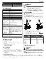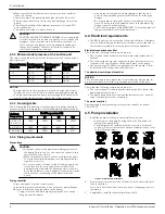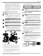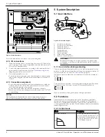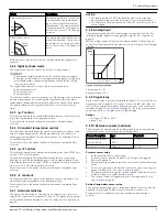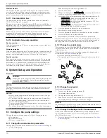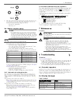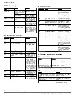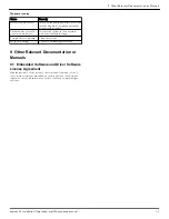
Table 2: Fault messages
Operating LEDs / Dis-
play
Cause
Solution
Power Off
Pump is not connected
or is incorrectly con-
nected
Check connection
Power failure
Check power supply
and circuit breaker
Status light Orange
Alarm for system prob-
lem
Check the displayed
alarm code and find
cause from table 8.3.
Status light Red
Pump failure
Check the displayed
error code and find the
cause from table 8.2.
Remote Off
Remote communica-
tion is deactivated
If the communication
does not work, check
the connection and the
configuration parame-
ters for communication
on the external con-
troller.
8.3 Fault and error codes
Error code
Cause
Solution
E01
Internal communication lost
Restart the pump
2
E02
High motor current
Restart the pump
2
E03
DC Bus overvoltage
Indicates excessive
power through the
pump. Confirm system
setup, verify correct
position and opera-
tion of check valves.
E04
Motor stall
Restart the pump
2
E05
Data memory corrupted
Restart the pump
2
E06
Voltage supply out of operating
range
Check the electrical
system voltage and
wiring connection.
E07
Motor thermal protection trip
Check the presence of
foreign material
around impeller and
rotor that cause over-
load. Check installa-
tion conditions and
temperature of the
water and ambient air.
Wait until the motor is
cooled. If the error
persists try to restart
the pump
2
.
E08
Inverter thermal protection trip Check installation con-
ditions and ambient
air temperature.
E09
Hardware error
Restart the pump.
E10
Dry run
Check for system leak-
age or fill the system.
8.4 Alarm codes
Alarm code
Cause
Solution
A01
Fluid sensor malfunction
Switch off the pump for 5
minutes and then power
on.
If the problem persists,
contact local B&G repre-
sentative.
A02
High temperature of the
fluid
Check water temperature
value
A03
Automatic speed reduction
to prevent inverter over-
heating
Check installation condi-
tions and rectify status of
the system
A05
Data memory corrupted
Switch off the pump for 5
minutes and then power
on. If the problem persists,
contact local B&G repre-
sentative.
A06
External temperature
probe malfunction
Check the probe and the
connection to the pump
A07
External pressure sensor
malfunction
Check the sensor and the
connection to the pump
A12
2–pump communication
lost
If both pumps show the
A12 alarm, check the con-
nection between the
pumps. If one of the pump
is switched off or shows an-
other error code, check the
section 8.1 and 8.2 to find
the problem
A20
Internal alarm
Switch off the pump for 5
minutes and then power
on. If the problem persists,
contact local B&G repre-
sentative.
8.5 Faults, causes, and remedies
The pump does not start
Cause
Remedy
No power.
Check the power supply and ensure that
it is properly terminated to the pump
power.
Tripped circuit breaker or
ground-fault protection de-
vice or the circuit breaker.
Reset power supply circuit breaker and
determine cause for overload.
The pump starts but the thermal protection is triggered after a short
time
Cause
Remedy
Incorrect wiring size or circuit break-
er rating not suitable for motor cur-
rent.
Check and replace the compo-
nents as necessary.
Thermal overload protection due to
excessive input.
Check the pump working con-
ditions.
Missing a phase in the power supply. Verify continuity and ensure
proper wiring connections.
2
Switch off the pump for 5 minutes and then power on. If the problem persists, contact service.
8 Troubleshooting
12
ecocirc XL Installation, Operation, and Maintenance manual


