background image

1  Introduction and Safety

1.1  Introduction

Purpose of this manual

The purpose of this manual is to provide necessary information for:

• Installation

• Operation

• Maintenance

CAUTION:

Read this manual carefully before installing and using the

product. Improper use of the product can cause personal in-

jury and damage to property, and may void the warranty.

NOTICE:

Save this manual for future reference, and keep it readily available at

the location of the unit.

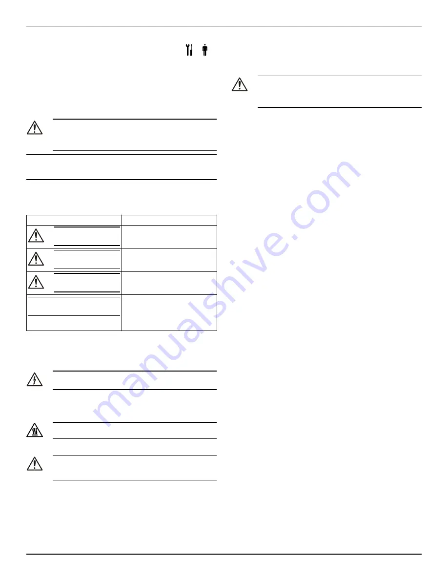
1.2  Safety terminology and symbols

Hazard levels

Hazard level

Indication

DANGER:


A hazardous situation which, if not

avoided, will result in death or se-

rious injury

WARNING:


A hazardous situation which, if not

avoided, could result in death or

serious injury

CAUTION:


A hazardous situation which, if not

avoided, could result in minor or

moderate injury

NOTICE:


• A potential situation which, if

not avoided, could result in

undesirable conditions

• A practice not related to per-

sonal injury

Hazard categories

Hazard categories can either fall under hazard levels or let specific sym-

bols replace the ordinary hazard level symbols.
Electrical hazards are indicated by the following specific symbol:

Electrical Hazard:


Hot surface hazard

Hot surface hazards are indicated by a specific symbol that replaces the

typical hazard level symbols:

CAUTION:

Qualified personnel

WARNING:

This product is intended to be operated by qualified person-

nel only.

1.3  Environmental safety

The work area

Always keep the station clean.

Waste and emissions regulations

Observe these safety regulations regarding waste and emissions:


• Appropriately dispose of all waste.

• Handle and dispose of the processed liquid in compliance with

applicable environmental regulations.

• Clean up all spills in accordance with safety and environmental

procedures.

• Report all environmental emissions to the appropriate authorities.

CAUTION: Radiation Hazard

Do NOT send the product to Xylem if it has been exposed to

nuclear radiation, unless Xylem has been informed and ap-

propriate actions have been agreed upon.

Electrical installation

For electrical installation recycling requirements, consult your local

electric utility.

Recycling guidelines

Always follow local laws and regulations regarding recycling.

FCC Statement — USA only (Federal Communications Commission)

This device complies with Part 15 of the FCC Rules. Operation is sub-

ject to the following two conditions:
1.

this device may not cause harmful interference and

2.

this device must accept any interference received, including inter-

ference that may cause undesirable operation.

This equipment has been tested and found to comply with the limits for

a Class B digital device, pursuant to Part 15 of the FCC Rules. These

limits are designed to provide reasonable protection against harmful

interference in a residential installation. This equipment generates,

uses and can radiate radio frequency energy and, if not installed and

used in accordance with the instructions, may cause harmful interfer-

ence to radio communications. However, there is no guarantee that in-

terference will not occur in a particular installation. If this equipment

does cause harmful interference to radio or television reception, which

can be determined by turning the equipment off and on, the user is en-

couraged to try to correct the interference by one or more of the fol-

lowing measures:

• Reorient or relocate the receiving antenna.

• Increase the separation between the equipment and receiver.

• Consult the dealer or an experienced radio/TV technician for help.

Changes or modifications not expressly approved by the manufacturer

responsible for compliance could void the user’s authority to operate

the equipment.

1.4  Product warranty

Coverage

Xylem undertakes to remedy defects in products from Xylem under

these conditions:

• The faults are due to defects in design, materials, or workmanship.

• The faults are reported to a local sales and service representative

within the warranty period.

• The product is used only under the conditions that are described

in this manual.

• The monitoring equipment that is incorporated in the product is

correctly connected and in use.

• All service and repair work that is done by Xylem authorized per-

sonnel.

• Genuine Xylem parts are used.

• Only Ex-approved spare parts and accessories that are authorized

by an Ex-approved Xylem representative are used in Ex-approved

products.

Limitations

The warranty does not cover defects that are caused by these situa-

tions:

• Deficient maintenance

• Improper installation

• Modifications or changes to the product and installation that are

made without consulting a Xylem authorized representative

• Incorrectly executed repair work

• Normal wear and tear

Xylem assumes no liability for these situations:

1  Introduction and Safety

ecocirc XL Installation, Operation, and Maintenance manual

3

Summary of Contents for ecocirc XL

Page 1: ...Installation Operation and Maintenance manual ecocirc XL ...

Page 2: ......

Page 3: ... connection 7 4 7 2 I O connections 8 4 7 3 Connection assignment 8 5 System Description 8 5 1 User interface 8 5 1 1 User interface locking unlocking 8 5 2 Functions 8 5 2 1 Control mode 8 5 2 2 Night set back mode 9 5 2 3 p T control 9 5 2 4 T Constant temperature control 9 5 2 5 p T control 9 5 2 6 T constant 9 5 2 7 External start stop 9 5 2 8 Analog Input 9 5 2 9 Signal relay 9 5 2 10 Externa...

Page 4: ... 8 5 Faults causes and remedies 12 9 Other Relevant Documentation or Manuals 13 9 1 Embedded Software and Driver Software License Agreement 13 Table of Contents 2 ecocirc XL Installation Operation and Maintenance manual ...

Page 5: ...th Part 15 of the FCC Rules Operation is sub ject to the following two conditions 1 this device may not cause harmful interference and 2 this device must accept any interference received including inter ference that may cause undesirable operation This equipment has been tested and found to comply with the limits for a Class B digital device pursuant to Part 15 of the FCC Rules These limits are de...

Page 6: ...efficient electronically commutated permanent magnet motor The pump is designed for systems with variable flow rates to opti mize pump operation thus reducing energy consumption The pump can be set to any one of the multiple operating modes available with each designed for a specific application to achieve high performance and maximum energy savings A single pump can handle heating cooling and plu...

Page 7: ...e sensor for details see section 5 2 10 of this manual Temperature sensor for details see section 5 2 10 of this manual Wireless module RS 485 module 4 Installation Precautions WARNING Observe accident prevention regulations in force Use suitable equipment and protection Always refer to the local and or national regulations legislation and codes in force regarding the selection of the installation...

Page 8: ...es must be correctly sized Pipe work must not transmit any load or torque to pump flanges Be sure to minimize any pipe strain on the pump Support suction and discharge piping by the use of pipe hangers near the pump Line up the vertical and horizontal piping so that the bolt holes in the pump flanges match the bolt holes in the pipe flanges Do not attempt to spring the suction or discharge lines i...

Page 9: ...ting assembly from motor housing b pay attention to the magnetic hazard listed before A defective O ring must be replaced An O ring is already availa ble inside the package as spare part 4 Properly align and tighten the four hex head screws 2 that affix the motor to the pump body 4 according to the torque table giv en below in a criss cross pattern M6 90 in lb M8 170 in lb M10 340 in lb CAUTION Ch...

Page 10: ...ce diagram 1 Control mode button 2 Control mode indicators 3 Parameter button 4 Parameter indicators 5 Setting buttons 6 Numeric display 7 Power indicator 8 Status Fault indicator 9 Remote control indicator Hot Surface Burn hazard During the normal operation the pump surfa ces may be so hot that only the buttons should be touched to avoid burns 5 1 1 User interface locking unlocking The user inter...

Page 11: ...rential temperature of the pumped media For details refer to the advanced functions manual on www bellgos sett com 5 2 7 External start stop The pump can be started or stopped via an external dry contact or a relay that is connected to terminals 11 and 12 The pump unit is provid ed by default with the terminals 11 and 12 jumpered See Figure 4 on page 8 NOTICE The pump provides 5 VDC through the st...

Page 12: ...ation occurs Cavitation can damage the internal components 6 1 Configure the pump settings Change the pump settings using one of the following methods User interface Bus communication Wireless communication 6 1 1 Change the communication parameters Change pump communication parameters See User interface page 8 1 Switch off the pump Wait until the power indicator light turns off 2 Switch on the pum...

Page 13: ...tions manual on www bellgossett com 6 2 2 Activate automatic two pump operation Once the communication cable is connected configure only the lead pump The twin pump submenu for this configuration is available at each power on when the drive is displaying SING which stands for Single Pump The following procedure must be executed during the start up phase of the pump 1 Enter the two pump sub menu wh...

Page 14: ...utes and then power on If the problem persists contact local B G repre sentative A02 High temperature of the fluid Check water temperature value A03 Automatic speed reduction to prevent inverter over heating Check installation condi tions and rectify status of the system A05 Data memory corrupted Switch off the pump for 5 minutes and then power on If the problem persists contact local B G repre se...

Page 15: ...s in pump Clean the system Worn out bearing Contact local B G representative 9 Other Relevant Documentation or Manuals 9 1 Embedded Software and Driver Software License Agreement With the purchase of the product the terms and conditions of the li cense for the software embedded on the product are considered ac cepted For more information see license condition on www bellgos sett com 9 Other Releva...

Page 16: ...d farms In more than 150 countries we have strong long standing relationships with customers who know us for our powerful combination of leading product brands and applications expertise backed by a legacy of innovation For more information on how Xylem can help you go to xyleminc com Xylem Inc 8200 N Austin Avenue Morton Grove Illinois 60053 USA Tel 847 966 3700 Fax 847 965 8379 www bellgossett c...

Reviews: