background image

• Make sure that the installation area is protected from any fluid

leaks, or flooding.

• If possible, place the pump slightly higher than the floor level.

• Provide shut-off valves on the suction and discharge sides of the

pump.

• The relative humidity of the ambient air must be less than 95%

non-condensing.

• This pump is suitable for indoor use only.

CAUTION:

CAUTION: PROPERTY DAMAGE HAZARD. It is not advisable

to install circulators in an attic or upper floor over finished liv-

ing space. If the circulator must be installed over head, or

over expensive equipment, provide adequate drainage in

the event of leakage.  Failure to follow these instructions

could result in property damage.

4.3.2  Minimum inlet pressure at the suction port

The values in the table below are the inlet pressures above the atmos-

pheric pressure.

Nominal Suction

Diameter

Fluid tempera-

ture 77°F (25°C)

Fluid tempera-

ture 203°F

(95°C)

Fluid tempera-

ture 230°F

(110°C)

1½”

4.5 PSI

16 PSI

25 PSI

2”

4.5 PSI

16 PSI

25 PSI

3”

7.5 PSI

19 PSI

28 PSI

NOTICE:

• Ensure that the suction pressure is never below the values speci-

fied above, as this could cause cavitation and damage the pump.

• The inlet pressure plus the pump pressure against a closed valve

must be lower than maximum admissible system pressure.

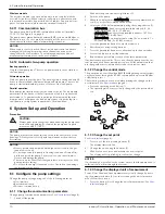
4.3.3  De-rating table

The following table indicates percent decrease in input power draw,

with the increase in temperature of circulating water and the ambient.

Ambient

temperature

Fluid Temperature (°C)

-10

60

95

110

32°F–77°F

(0°C–25°C)

100%

100%

100%

100%

86°F (30°C)

100%

100%

80%

70%

104°F (40°C)

100%

100%

70%

55%

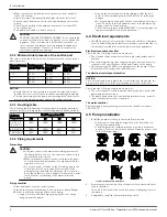
4.3.4  Piping requirements

Precautions

CAUTION:

• Use pipes suited to the maximum working pressure of

the pump. Failure to do so can cause the system to rup-

ture, with the risk of injury.

• Make sure that all connections are performed by quali-

fied installation technicians and in compliance with the

regulations in force.

• Do not use a shut-off valve on the discharge side in the

closed position for more than a few seconds. If the

pump must operate with the discharge side closed for

more than a few seconds, a bypass circuit must be instal-

led to prevent overheating of the water inside the

pump.

Piping checklist

• Pipes and valves must be correctly sized.

• Pipe work must not transmit any load or torque to pump flanges.

• Be sure to minimize any pipe-strain on the pump:

• Support suction and discharge piping by the use of pipe

hangers near the pump.

• Line up the vertical and horizontal piping so that the bolt-

holes in the pump flanges match the bolt-holes in the pipe

flanges.

• Do not attempt to spring the suction or discharge lines in po-

sition. This may result in unwanted stress in the pump body,

flange connections and piping.

• The code for pressure piping (ANSI B31.1) lists many types of

supports available for various applications.

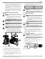
4.4  Electrical requirements

• The NEC and local codes must be followed at all times. If a branch

circuit is fitted with ground fault circuit breaker, ensure that the cir-

cuit breaker is suitable for use with inverter-driven appliances.

Electrical connection checklist

Check that the following requirements are met:

• The electrical wires are protected from high temperature and vi-

brations.

• The current type and power supply voltage connection must cor-

respond to the specifications on the name plate on the pump.

• Use wires at least 14 AWG to supply power to the pump. Follow

all local and NEC wiring codes and practices.

The electrical control panel checklist

NOTICE:

The electrical supply must match the electrical rating of the pump. Im-

proper combination could fail to guarantee protection of the unit.

Check that the following requirements are met:

• The control panel circuit breaker be sized properly to protect the

pump against short-circuit.

• The pump has built in overload and thermal protection, no addi-

tional overload protection is required.

The motor checklist

Electrical supply and grounding wires must be suitable for at least

194°F (90°C).

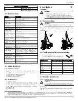
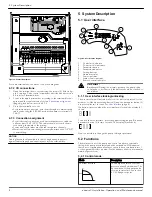
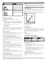
4.5  Pump installation

1.

Install the pump according to the liquid flow direction.

• The arrow on the pump housing shows the flow direction

through the pump body.

• The pump must be installed with the motor in a horizontal

position. For more information about allowed positions, refer

to the following image:

Figure 1: Allowed pump installation

2.

If necessary, rotate the position of the motor for better visibility of

the user interface.
Section 4.6 below describes the procedure of changing of motor

orientation.

3.

If applicable, install the thermal insulation shells.

4  Installation

6

ecocirc XL Installation, Operation, and Maintenance manual

Summary of Contents for ecocirc XL

Page 1: ...Installation Operation and Maintenance manual ecocirc XL ...

Page 2: ......

Page 3: ... connection 7 4 7 2 I O connections 8 4 7 3 Connection assignment 8 5 System Description 8 5 1 User interface 8 5 1 1 User interface locking unlocking 8 5 2 Functions 8 5 2 1 Control mode 8 5 2 2 Night set back mode 9 5 2 3 p T control 9 5 2 4 T Constant temperature control 9 5 2 5 p T control 9 5 2 6 T constant 9 5 2 7 External start stop 9 5 2 8 Analog Input 9 5 2 9 Signal relay 9 5 2 10 Externa...

Page 4: ... 8 5 Faults causes and remedies 12 9 Other Relevant Documentation or Manuals 13 9 1 Embedded Software and Driver Software License Agreement 13 Table of Contents 2 ecocirc XL Installation Operation and Maintenance manual ...

Page 5: ...th Part 15 of the FCC Rules Operation is sub ject to the following two conditions 1 this device may not cause harmful interference and 2 this device must accept any interference received including inter ference that may cause undesirable operation This equipment has been tested and found to comply with the limits for a Class B digital device pursuant to Part 15 of the FCC Rules These limits are de...

Page 6: ...efficient electronically commutated permanent magnet motor The pump is designed for systems with variable flow rates to opti mize pump operation thus reducing energy consumption The pump can be set to any one of the multiple operating modes available with each designed for a specific application to achieve high performance and maximum energy savings A single pump can handle heating cooling and plu...

Page 7: ...e sensor for details see section 5 2 10 of this manual Temperature sensor for details see section 5 2 10 of this manual Wireless module RS 485 module 4 Installation Precautions WARNING Observe accident prevention regulations in force Use suitable equipment and protection Always refer to the local and or national regulations legislation and codes in force regarding the selection of the installation...

Page 8: ...es must be correctly sized Pipe work must not transmit any load or torque to pump flanges Be sure to minimize any pipe strain on the pump Support suction and discharge piping by the use of pipe hangers near the pump Line up the vertical and horizontal piping so that the bolt holes in the pump flanges match the bolt holes in the pipe flanges Do not attempt to spring the suction or discharge lines i...

Page 9: ...ting assembly from motor housing b pay attention to the magnetic hazard listed before A defective O ring must be replaced An O ring is already availa ble inside the package as spare part 4 Properly align and tighten the four hex head screws 2 that affix the motor to the pump body 4 according to the torque table giv en below in a criss cross pattern M6 90 in lb M8 170 in lb M10 340 in lb CAUTION Ch...

Page 10: ...ce diagram 1 Control mode button 2 Control mode indicators 3 Parameter button 4 Parameter indicators 5 Setting buttons 6 Numeric display 7 Power indicator 8 Status Fault indicator 9 Remote control indicator Hot Surface Burn hazard During the normal operation the pump surfa ces may be so hot that only the buttons should be touched to avoid burns 5 1 1 User interface locking unlocking The user inter...

Page 11: ...rential temperature of the pumped media For details refer to the advanced functions manual on www bellgos sett com 5 2 7 External start stop The pump can be started or stopped via an external dry contact or a relay that is connected to terminals 11 and 12 The pump unit is provid ed by default with the terminals 11 and 12 jumpered See Figure 4 on page 8 NOTICE The pump provides 5 VDC through the st...

Page 12: ...ation occurs Cavitation can damage the internal components 6 1 Configure the pump settings Change the pump settings using one of the following methods User interface Bus communication Wireless communication 6 1 1 Change the communication parameters Change pump communication parameters See User interface page 8 1 Switch off the pump Wait until the power indicator light turns off 2 Switch on the pum...

Page 13: ...tions manual on www bellgossett com 6 2 2 Activate automatic two pump operation Once the communication cable is connected configure only the lead pump The twin pump submenu for this configuration is available at each power on when the drive is displaying SING which stands for Single Pump The following procedure must be executed during the start up phase of the pump 1 Enter the two pump sub menu wh...

Page 14: ...utes and then power on If the problem persists contact local B G repre sentative A02 High temperature of the fluid Check water temperature value A03 Automatic speed reduction to prevent inverter over heating Check installation condi tions and rectify status of the system A05 Data memory corrupted Switch off the pump for 5 minutes and then power on If the problem persists contact local B G repre se...

Page 15: ...s in pump Clean the system Worn out bearing Contact local B G representative 9 Other Relevant Documentation or Manuals 9 1 Embedded Software and Driver Software License Agreement With the purchase of the product the terms and conditions of the li cense for the software embedded on the product are considered ac cepted For more information see license condition on www bellgos sett com 9 Other Releva...

Page 16: ...d farms In more than 150 countries we have strong long standing relationships with customers who know us for our powerful combination of leading product brands and applications expertise backed by a legacy of innovation For more information on how Xylem can help you go to xyleminc com Xylem Inc 8200 N Austin Avenue Morton Grove Illinois 60053 USA Tel 847 966 3700 Fax 847 965 8379 www bellgossett c...

Reviews: