SECTION 574-504-720
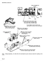
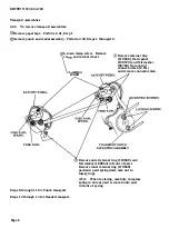
cable connector
P201 from logic card and
lift out switch assembly.
RELAY CONNECTOR
(See 9)
Loosen screw (nut on later units)
and remove ground strap running
from punch frame ( 412390 strap).
Note:
Steps 11 and 12 need no be
performed to remove Punch and Reader.
Remove power supply ac
cable connector (P-601).
Remove punch and reader
assembly from housing.
Lift straight up.
(!)Remove cable connectors
from logic card.
/
Remove 2 circuit card
bracket screws.
�----
J-'
�
Slide logic card re
arwar
d out
of plastic guides and housing.
9
Remove relay cable connector located
at front of power supply circuit card.
Note:
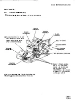
During reassembly, be certain that the reader tight tape arm remains outside the opening in the
cover.
Page 4


