background image

Summary of Contents for TOUCH-A-MATIC 2872A 1M

Page 1: ...arts Record Disable and Dial Intermix Features 10 Single Une Service 12 Head Telephone Set 12 COMPONENT LOCATION AND ACCESS INFORMATION 12 Location Of Components 12 CONTENTS PAGE Mounting Cord 13 Network Terminals 16 Power Supply PSB Terminals 16 Une Key Removal 17 Faceplate Removal 17 Handset Cradle Removal 17 Housing Removal 17 4 CONNECTIONS 18 5 OPERATION 18 Record A Number Into Memory 18 Chang...

Page 2: ...is reissued to Show 2872A1M telephone set MD Revise Fig 1 through 5 7 through 12 and 14 Revise Tables A through G J and N Add Fig 13 Show 2872A1 faceplate MD Add Tables K L and M Eliminate connection information for 82A connecting block Add D 180818 Kit of Parts Record Disable and Dial ntermix Features Add reference for use of station head telephone adapters Since this reissue covers a general rev...

Page 3: ...e set Integrated circuit RC TOUCH TONE oscillator Integrated circuit memory ISS 4 SECTION 503 603 101 Surge protector Polarity guard removable for dry circuit application Common audible ringing Buzzer Busy lamp diode Line pickup buttons convertible to nonlocking signal buttons Memory buttons from which to select preprogrammed telephone numbers for automatic dialing Capability to record and automat...

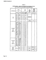
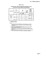
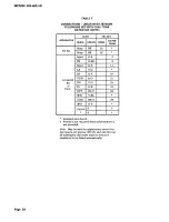
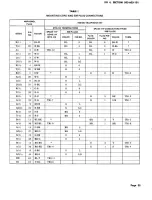
Page 4: ...ily depressed extinguishes the RECORD lamp indicating that the dialer is switched out of the record mode WAIT button nonlocking when momentarily depressed during recording operation enters a code into memory to initiate a halt in the automatic dialing sequence used where access digit s required 3 INSTAUATION STANDARD INSTAUATION 3 01 Make all wiring changes and telephone set modifications Table A ...

Page 5: ...nting screw holds the duplex outlet in the box Note The 958 type power unit must be located no closer than 1 112 feet from the telephone set in order to prevent a noise problem 3 04 The station number card retainer 812558039 P 25E803 snaps into the faceplate below the dial 3 05 The directory sheets Fig 2 fit over the buttons of the memory and are held in place by the faceplate Additional sheets ar...

Page 6: ...SECTION 503 603 101 TERMINAL BOAR D TBl BUZZER M OUN I N G Fig 3 2872A2M Telephone Set With Faceplate Handset and Handset Cradle Removed Page 8 ...

Page 7: ...press a memory button of a memory location used in Step 3 to verify retention of memory 6 Dial the appropriate code for ring back to test the ringer ISS 4 SECTION 503 603 101 7 Check operation of the logic reset switch by pressing the RECORD button RECORD lamp will come on and subsequently pressing an unoperated line button The RECORD lamp must go out 8 If equipped with one touch calling option D ...

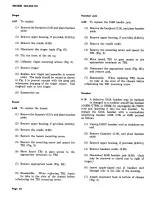
Page 8: ... off the detail at the bottom of the cover Fig 2 and trim edge as required 7 Verify correct operation of the option 8 Reassemble set D 180494 Kit of Ports 2 4 Wire Service 3 10 To install 1 Proceed as described in 3 17 Page 10 2 Make connections per Table G 3 Mount the kit assembly to the chassis with the screws provided Fig 4 D 180818 Kit of Ports Record Disable and Dial Intermix Features 3 11 To...

Page 9: ...wo screws provided Note Ifthe one touch calling switch D 180493 Kit of Parts has been provided it must be removed The PSB terminals where the switch leads were connected Table C or E must be strapped together The one touch calling option an no longer be turned off by the subscriber 7 Connect switch lead connectors to post terminals on memory board per Table K 8 With feature switch in OFF position ...

Page 10: ... per Table L 5 Reassemble set and install a 2870B1 faceplate of the appropriate color Note If set was originally equipped with a 2872A1 87 faceplate refer to 6 11 Head Telephone S t 3 13 To install Page 12 1 Remove housing 3 21 2 Access PSB terminal area 3 17 3 Remove cradle 3 20 4 Thread jack set cord through hole in rear of housing and make connections per appropriate table provided for Plantron...

Page 11: ...pe key module at the telephone set end The conductors terminated in the 508 type plugs provide the major line service requirements Spade tipped conductors are provided for auxiliary control functions or options and are terminated dir ectly on associated equipment terminal boards or stored Note Sets manufactured prior to fourth quarter 1976 were equipped with 050AM 87 mounting cords The major diffe...

Page 12: ... R CONNECT TEL SET FROM NOTE 11 CONTUNIT NOTE 31 TOPSB FROM TERM 56A 668 2 19 1 11 28 10 12 2 Ft 5 11 17 11 36 18 34 9 25 17 33 8 24 PSB10 PSB20 10 16 16 17 18 20 21 4 7 13 8 14 16 3 18 29 19 2 17 11 35 34 20 33 j 29 j 27 27 36 36 j To reduce loudspeaker volume move SP2 lead to terminal 24 56A or 30 66B Inaulate and otore 8IrV and V 8L leads In connector cable No teo 1 Plug telephone oet mounting ...

Page 13: ...E 5 TOPS8 FROM TERM 55A 558 T1 V G 2 19 1 R1 G V 11 28 10 A1 12 2 AG V S Ft 5 11 LK S V 17 11 35 SPO o v 34 3 18 Ror R1 18 34 RorR1 9 25 Bor B1 17 33 B or B1 8 24 Input G R 2 PB 0 BK 9 Input G R 11 LK Y G 17 DT Q Y 19 VDD R 0 21 DR Y 0 24 PL Q R 25 OTT BL Y 26 SPR Y BL 27 COM BK Q 29 SPO G Y 34 s 28 Switch s 29 CE BL BK 10 B BK BL 15 SHa R BL 16 LK BL R 17 SHi G W 18 PFR BL V 20 VDD W G 21 TO 1498...

Page 14: ...nal 20 insulate and store 3 Both power nit and 20128 transformer must be connected for speakerphone operation 4 When mstalhng the D 180493 Kit of Parts remove 8K strap leads from PS8 terminals 19 26 and 29 Insulate and store 5 When 55 A control unit is used it must be the type modified for TOUCH TONE and strap terminals 20 and 21 55 A or 4 and 5 55 8 were required with the D50AM 87 whereas individ...

Page 15: ...the key completely out of the set 5 Replace key by reverse procedure ISS 4 SECTION S03 603 101 Faceplate Removal 3 19 Removal will differ depending on faceplate provided a The 2872B1 faceplate is held in place by a spring clip attached to the 870A1U upper housing To disengage the faceplate lift up the tab which protrudes from the center of the back edge of the faceplate Note The 2872B1 faceplate i...

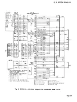
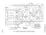
Page 16: ...dure 4 CONNECTIONS 4 01 Telephone set connections are shown in Fig 8 and Table I Page 18 Caution Some conductor assignments are not standard Table 1 4 02 Refer to Table A for connection reference for all options 4 03 A partial functional schematic is shown on Fig 14 5 OPERATION Record A Number Into Memory 5 01 To record 1 Remove the faceplate 3 19 2 Write or type the desired name and telephone num...

Page 17: ...aling b For sets equipped with the dial tone detector only go off hook listen for dial tone and depress the desired memory button c For sets equipped with the one touch calling option with speakerphone and dial tone detector simply depress the memory button ISS 4 SECTION 503 603 101 LAST NUMBER DIALED Feature Note If set is equipped with a D 180818 Kit of Parts and dial intermix feature is provide...

Page 18: ...mory The RECORD lamp will not light at any time but depressing the RECORD OFF button will remove the set from the last number dialed mode and allow additional automatic dialing b Dial Intermix D 180818 Kit of Parts With the switch in the ON Page 20 position manually and automatically dialed digits may be intermixed as desired Operation of the RECORD OFF button is not required Note In this mode the...

Page 19: ...row of pins The flat power supply cable should not be twisted It should form a loop as shown in Fig 5 when connected to the board 6 Reassemble set 7 Test per 3 07 6 05 To replace 1 Proceed per 3 17 2 Loosen the four captive mounting screws of the memory Fig 4 3 Gently raise the left side of the memory and rotate to position shown in Fig 5 This will expose 10 position dial connector Caution Do not ...

Page 20: ...mounting screw Page 22 Handset Jack 6 09 To replace the 616B handst jack 1 Remove the faceplate 3 19 and place handset aside 2 Remove upper housing if provided 3 21 b 3 Remove the cradle 3 20 4 Remove the mounting screw and spacer for TB1 Fig 3 5 Move board TBl to gain access to the appropriate terminals on TB2 6 Disconnect the appropriate leads Fig 8H and remove jack 7 Reassemble When replacing T...

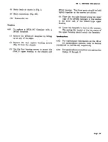
Page 21: ...3 101 870A1 housing The three parts should be held tightly together as the screws are driven 4 Place the two tabs located along the lower edge of the 2872B1 faceplate in the notches in the lower side of the 870A1U type upper housing 5 Lower the faceplate to rest on the memory The spring clip located at the top center of the upper housing should retain the faceplate Speakerphone 6 12 For maintenanc...

Page 22: ...K 8L R of Parts SHi G W PFR 8L V VDD W G 8581 Power AC1 8K Unit Note 3 AC2 y 958 Type AC1 R Power Unit Note 3 AC2 G Insulated and stored t Terminal on network Notes 2 11 Note 2 Ft 17 PS8 10 PS8 20 10 15 16 17 18 20 21 BR V AC1 V 8R AC2 8L V 21 V 8L 46 1 Plug mounting cords of telephone set 108A loudspeaker and 660A transmitter into 828 connecting block Install option plug in ringer cutoff mode 2 F...

Page 23: ...TORE THE BL V PAIR AT THE KEY EQUIPMENT NO l INSUlATE AND STORE THE BL V AND V IlL MOUNTING CORD LEAilS FIVH PS8 TERMINALS 4 A 9S B TYPE POWER UNIT IS REQUIRED FOR EACH TELEPHONE SET NlMIERS IN PARENTHESES INDICATE CONNECTOR PIN N RS r c p __ TO KEY T L PHOIIE SYSTEM NOH 2 ROW I 10 1 f HI II 26 5 I II 20 1 H U I 31 10 I 21 30 5 H_I II 36 15 I 31 40 1 1I II 41 20 I 4142 so a n II 46 I I 21 25 I I I...

Page 24: ...G 2 Rl G V H Tel Al Note 2 Set AG V S Ft LK s v 17 SPO O V 34 Strap O V 10 to 35 lriput G R 2 PB Q BK 9 Input G R 11 LK Y G 17 DT Q Y 19 D 180493 VDD R O 21 Kit DR Y 0 24 of PL O R 25 Parts Note 4 OTT BL Y 26 SPR Y BL 27 COM BK O 29 SPO G Y 34 s 28 SWITC s 29 CE BL BK 10 B BK BL 15 D 180492 SHa R BL 16 Kit of LK BL R 17 Parts SHi Note 3 G W 18 PFR BL V 20 VDD W G 21 BR V 8581 Power AC1 BK AC1 Unit...

Page 25: ... V BL 4 1 Plug mounting cords of telephone set lOSA loudspeaker and 680A transmitter into 82B connecting block Install option plug in ringer cutoff mode 2 For lAl or 1A2 KTS connect link between 2 and Al For 1A KTS connect link between 19 and Al TO 3 When installing D 180492 Kit of Parts disconnect BK strap from PSB 10 insulate and store disconnect BK lead from PSB 20 insulate and store 4 Remove B...

Page 26: ...R 2 PB 0 BK 9 Input G R 11 LK Y G DT 0 Y 19 VDD R 0 21 D 180493 Kit DR Y 0 24 of PL 0 R 25 Parts DTT BL Y 26 SP R Y BL COM BK 0 29 SPO G Y Switch s t s Insulated and stored t Switch is not required when speakerphone is not provided Note May be used for applications where first dial tone is no t precise 350 Hz and 440 Hz but all subsequent dial tones must be precise if number is to be dialed automa...

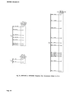
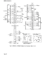
Page 27: ...D CC CF Y Z p _STRAP BK I B 22 IBR W l FIG L ft f lcii5t STRAP 81 BK Gl 1 _ I Y O l______________ z _ED R 1 W Jic L 2 20 T 0 Rl i PL 0 W 10 50 I BL _ Ylr_______ J Zl _____ o TT 4 20 IY Bll y i SPR IN LRS I BATTERY 1 0 1Y _ l r 4 4 1 4 B Y 1 l 1 I 1 14 2 I I I I BK l L______r l l I B R NOTES 1 FOFI 38 SPEAKERPHONE WITH 1498 ADAPTER OR 4A WITH 828 CONNECTI NG BLOC K USE tO VI LE AD FOR 4A SPEAKERPHO...

Page 28: ... O WIRING BOARD CD 110492 I I 2 s 7 4 FIG E ONE TOUCH CALLING SWITCH 0 1104931 INf UT IG RI 0 IKI INPUT G R Lk Y GJ OT 0 Y I YOO 0 01 OR CY 0 PL 0 RI OTT II YI Y ll cow IBK 01 SPO G Y FIG 0 DIAL TON DI T CTOR 0 11 0411 I 7 t 12 10 4 s II L _ _ Fig 8 2872A1M ar 2872A2M Telephone Set Connections Sheet 2 of 5 Page 30 ...

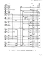
Page 29: ...h I I FIG I FIG Ll L3 c B c F cA c E c 0 ISS 4 SECTION 503 603 101 FIG G DIAL COMMON SWI TC IG WI IR GI IRI 101 IILl IW IL l FIG 8 IWI IV BL I IS RI IBR W I DIAL fREQUENCY SWITCHES H2 v qJ 4J 0 G WI IO Wl L2 f iG A Fig 8 2872A1M or 2872A2M Telephone Set Connections Sheet 3 of 5 Page 31 ...

Page 30: ...NGER I BKI FIG I TBI I U J J 2 P j 3 J r D 7 1 U _L _ _ I R Ill IBKI U IIK 1111 IR YI IY IR IR 81 IlK Ill Clll 47U IO Wl 11 Y I FI G J fiG W Ill 11 W Pll I 425K OR 4228 TYPE NETWORK FI G F IRI IIL W fi8 J L2 I taJ2J G taJ2J j 101 1o i 1 L _ _ _ l l 0 IY 91 T IV 01 FIG K NOTES I PHYSICAL TEAMI LAYOUT OF 2 PHYSICAL T ERMINAL LAYOUT r 6 425K N T II Cfft 4228 TYPE NET M Rt 00 T F 0 0 RR IR GI 0C S0 0S...

Page 31: ...3 R 01 AC PWR I8L V AC PWR IV 8L R3 10 RI L4 10 BKI LG4 I8K OI 4A 4 H I8K 8L 8R IYI T4 IR s Rl f Y 81 IY S FIG I R4 S RI L5 IS BKI ill 8K 5H ORS faK iii lSI AI 8 0 W lVI T5 IBK GI SG IBR YI TIP IGI 8L Y BR RING AI R5 G BKI INSULATE AND STORE I ISS 4 SECTION 503 603 101 FIG L eo8 PLUGS IWI I8RI 2 8R W L IW 8RI LG I 2 8LI 3 IG WI L W l LG IW 01 I 2 IW 8LI 3 4 18L WI 6 IBL R L R BLI LG IW SI I 2 W BR...

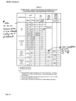
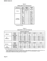
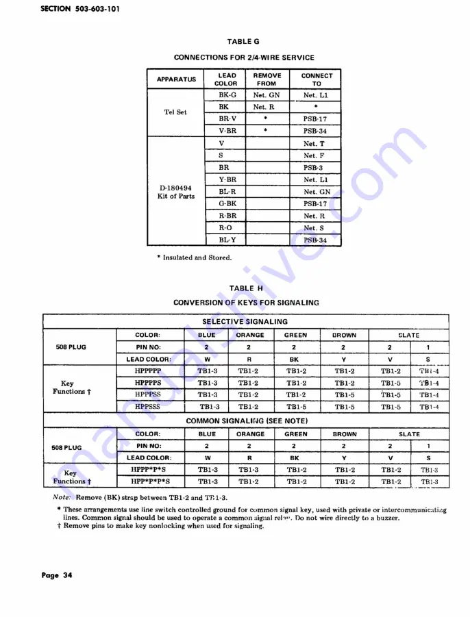
Page 32: ...Bl 2 TBl 2 Functions t HPPPSS TBl 3 TBl 2 TB1 2 TBl 5 HPPSSS TBl 3 TBl 2 TBl 5 TBl 5 COMMON SIGNALHm SEE NOTE COLOR BLUE ORANGE GREEN BROWN 508 PLUG PIN NO 2 2 2 2 LEAD COLOR w R BK y Key HPPP P S TB1 3 TBl 3 TBl 2 TBl 2 Functions t HPP P P S TB1 3 TBl 2 TBl 2 TDl 2 Note Remove DK strap between TBl 2 and Tn1 3 LATE 2 1 v s TBl 2 TIH 4 TBl 5 l Bl 4 TBl 5 TBl 4 TBl 5 TBl 1 SLATE 2 1 v s TBl 2 TBI 3 ...

Page 33: ...BL 1 BL 1 W 0 L 1 3 G W BL L LG 1 28 W G BL LG R 2 4 BR W 0 6 T 2 29 W BR 0 3 B 2 5 S W 0 2 R T B1 2 A 2 30 w s 0 1 L 2 6 BL R 0 L LG 2 31 R BL 0 LG R 3 7 0 R G 6 T 3 32 R 0 G 3 B 3 8 G R G 2 BK TB1 2 A 3 33 R G T B1 7 G 1 S W T B1 7 L 3 9 BR R G L LG 3 34 R BR G LG R 4 10 S R BR 6 T 4 35 R S BR 3 B 4 11 BL BK BR 2 y TB1 2 A 4 36 BK BL TB 1 9 BR 1 BR TB1 9 L 4 12 0 BK BR L LG 4 37 BK 0 BR LG R 5 1...

Page 34: ... BL 44 Y BR TB1 6 R or Rl 20 S Y TBl 13 B or B1 4 5 Y S Net K AC1 1 21 BL V PSB 30 AC2 t 46 V BL PSB 31 SPO 22 0 V Spare 47 V 0 Net T RU 23 G V TU 48 V G IR 24 BR V In 49 V BR LK 25 S V AG 50 v s Tip s Ring s Pink Pink Pink Pink Pink Insulate and store t 95Bl Power Unit Touch A Matic Power Supply 1 Designations for speaketphone options Refer to Tables B through E Nonstandard pin numbers Page 36 50...

Page 35: ... NOTE 21 WDC BK 1 VDD R 2 2 RCRD BK 3 3 Insulate and store t Single pin connector Notes I These are connectors attached to the switch leads A sin gle pin connector with a BK lead and a double pin connector with a R and BK lead 2 When this optio n is provided the LAST NUMBER DIA LED LND feature is disabled and the 32nd memory may be used just as any other memory ISS 4 SECTION 503 603 101 TABLE L CO...

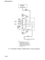
Page 36: ...TBI 4 S I PU 2 V 39 r NETWORK R Bt TBI I G HOLD T BL TBI 3 STRAP II TBI 2 W INSULATE ANO STORE FOR ADD ON CONFERENCING CONVERT THE 5TH PU TO NONLOCKING IREIIOVE PINI FOR MULTILINE EXCLUSION CONVERT THE 5TH PU TO NONLOCKING REWOVE PINI i WITHOUT STATION BUST LAMP WITH STATION BUSY LAMP 1 HOLD OPTION Fig 9 I Hold Exclusion Station Busy Lamp and Add On Conferencing 1 A1 and 1A2 KTS Showing 5th Key Mo...

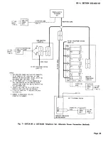
Page 37: ...UIITIIKl COIIO 1 98 ADA TER A258 CAI I E TO KEY TELEPHONE SYSTEM ISH NOTE l OIOR COIIO 111 011 CAI I E NOTE DISCONNECT THE V 81 IN THE CABLE AT KEY SYSTEM END ISS 4 SECTION S03 603 101 Fig 10 Biock Diagram 2872A1M or 2872A2M Telephone Set Using 3B Speakerphone Page 39 ...

Page 38: ...E SYSTEM NOTE 21 1 STRAP NEC SSARY Otf Y IF SET IS ALSO EQUIPP 0 Wi ll DIAL TONE DETECTOR TO PROV IDE ONE TO UCH CALLING OPT IO N 2 IF POWER IS P lOV I OED THROUGH KEY CABLE USE BR V PAIR FOR 85 TYP POH R UNI T AND STRAP 24 TO AC1 AND 49 TO AC2 O N 828 COt I ECTING BLOCK Fig 11 Biock Diagram 2872A1M or 2872A2M Telephone Set Using 4A Speakerphone Page 40 ...

Page 39: ...wl I I W BLI I CA i DIAL coM sw I5 L J NETWORK R OI FW4 RFiCB R GI l Jl R BRI LEGEND WITHOUT 4 WIRE OPTION WITH 4 WIRE OPTION RI 3 LAY I I 0 IKI n _ H 1 MB7 1 I NSULATE AND STORE R 4 WIRE CONTROL VI 51 F NETWORK BLI GI 1 HOLD 27 lA W 01 Y BLI 2 WI TBI I 3 TO OTHER TBI 2 L ADS PU Fig 12 2872A1M cw 2871A2M Telephone Set 2 4 Wire Connections Page 41 ...

Page 40: ...O STORED WITHOUT RESTRICTED DIALING FACTORY WIRED WITH RESTRICTED DIALING NOTES 1 REVERSE POLARITY ON TIP ANO RING LEADS ON ALL LINES WITH RESTRICTED DIALING 2 FOR 2872A1M SET Y FOR 2872A2M SET BL 3 FOR 2872A1MSET BL FOR 2872A2M SET Y Fig 13 2872A1M or 2872A2M Telephone Set Connections for Restricted Dialing Option ...

Page 41: ...I PSB 10 I I 61 0 MA3 I I 1111 V 0180493 r MB7z I I KIT G VI PS8 II IG RI 10 YI R L 811 eLI 8L eiQ PSB 15 I I fY I DIAL I I osc I 0 V I f f r I PSB 34 PSB 18 I P3 15 1 I MB7e L _ ______ _ _j 101 IBK BL l l PU S R 0 Y 0 j LS k 3011 R 811 0 I c NET I R 8111 58 IZ m 16 G W TB2 4 PS j 6 NOTE ZIL 3 PSB 5 I I O W YI b 5 TB I 12 LS TBI 11 l V SI R BLI 8R WITH POLARITY Gl IMO WITHOUT POt ARITY GUARO NET F...

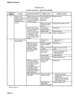
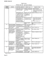
Page 42: ...t or jack in telephone set Dial tone present but 12 pin connector 1 Check connector insertion sidetone absent No or dial not 2 Replace dial audible TOUCH TONEfiD properly inserted signal on pins on power supply board Defective 61GB jack Replace 61GB jack Defective network Replace telephone set 3 Cannot manually dial Clicking sounds or Bridged set off hook Place bridged set on hook when off hook da...

Page 43: ...h position to button is depressed Kit of Parts in ON OFF position AC power unit not Check or replace power unit plug ed in or defec should read 13 4 to 18 VAC tive across screw terminals 30 and 31 on PSB Open in IW Check IW and connection Memory RECORD Clear stuck button OFF or WAIT button stuck down Defective lamp or Replace memory lamp driver circuit Defective logic reset Replace line key switch...

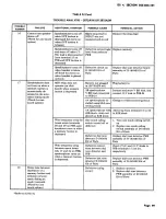
Page 44: ...dial properly Did not record 1 Record per 5 01 from memory properly 2 See No 7 MB7 relay does not Battery not plugged Plug battery in operate no clicking in 2872A2M tel sound heard when set memory button is Memory not securely Tighten memory mounting depressed No audi ble TOUCH TONE mounted screws signal present Open circuit in Check for proper strap lead power path connections on PSB See Fig 8 B ...

Page 45: ...fter tacts or defective cir 2 Replace dial tone detector pausing momentarily cuit components PW8 assembly of 0 180493 at the wait space Kit of Parts if option is on a train of recorded provided digits 10 Cannot manually dial With a strap lead Defective circuit o r 1 Check connections per Table off hook C or ac between screw terminals connections on 8 C D orE power failure condi 10 and 15 on PSB ca...

Page 46: ...utton is Defective switchhook Replace telephone set phone option released a b contacts 13 RECORD lamp does Speakerphone indicator Handset off hook Place handset on hook not turn off when lamp does not turn on speakerphone ON Line lamp is lit button is depressed With temporary strap LK relay circuit Replace D 180492 Kit of Parts Wired for speaker lead added between defective on phone option screw t...

Page 47: ... the auto to PSB 34 malic dialing mode Wired for one 4A speakerphone in Change to 82B connecting block touch option stalled using 82A con necting block 4A speakerphone with Add strap from terminal 10 to 35 82B block strap not in 82B block placed on 82B block With temporary strap be One touch calling 1 Turn one touch calling switch tween screw terminals switch turned off or on 28 and 29 on PSB spea...

Page 48: ...Noise on line MB7 relay does not Battery not plugged operate no click heard in 2872A2M tel set when memory button Precise TOUCH is depressed TONE dial tone may not be present Memory not securely mounted Improper installation of dial tone detector 0 180493 Same as above Improper connection Addition of strap lead to or defective between PSB terminals memory 26 and 29 does not correct problem Additio...

Reviews: