background image

Summary of Contents for TOUCH-A-MATIC 2872A1M

Page 1: ... 19 Installation Check Procedure 8 5 OPERAI_ION 19 OPTIONAL APPARATUSINSTALLATION 10 A Record A Number Into Memory 19 A D 180492 Kit of Parts With Speakerphone 10 B Change A Number In Memory 20 B D 180493 Kit of Parts Dial Tone C Delete A Number From Memory 20 Detectorand One Touch Calling Switch 10 D Automatically Dial A Number From Memory 20 C D 180494 Kit of Parts 2 4 Wire Service 11 E LAST NUM...

Page 2: ...late 24 Show 2012B transformer MD K Speakerphone 25 Show 3B speakerphone MD 1 GENERAL 1 03 The 2872AIM MD or 2872A2M telephone 1 01 This section contains information on the set is factory wired for use with 1A1 1A2 2872AIM MD or 2872A2M TOUCH TONE or 6A key telephone systems KTS They may Dial TOUCH A MATIC telephone set Fig 1 be converted Table J for use with 1A KTS HANDSET MEMORY 35 TYPE DIAL HOU...

Page 3: ...a application dialing automatic dialing of 31 frequently called numbers and a LAST NUMBER DIALED scratch pad memory B OptionalFeatures 2 02 The 2872A2M telephone set differs from the 2872AIM set only in the battery circuit 2 04 Optional Features Refer to Table A The 2872A2M set has a battery interlock circuit that prevents the set from dialing automatically if the battery is not plugged in Also th...

Page 4: ...be telephone set intermixed without depressing RECORD OFF button Memories cannot be altered Decorative Faceplate 2872B1 108 Teak and LAST NUMBER DIALED feature is Woodgrain or2872Bl 109 Walnut Woodgrain inoperative i c The 2872A2M set is comprised of the following Station Busy Lamp busy lamp diode wired component parts in set Housing Lower 870A1 2 4 Wire Service Housing Upper 870AIU used only with...

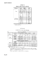
Page 5: ...former 11 B C 149B Adapter B C D 180492 Kit of Parts 9 C D E D 180492 Kit of Parts 9 D E One Touch Calling C E Speakerphone 9 B Dial Tone Detector D 180493 Kit of Parts 9 D C E F Station Busy Lamp 10 I Hold 10 Signaling H Exclusion Multiline 10 Ad d On C on fere nce 10 Amplifying Handset G6BM O7BM or G8BM Handset 9 H 2 4 Wire Service D 180494 Kit of Parts 13 G Dry Circuit without Polarity Guard 9 ...

Page 6: ...M MD or 2872A2M sets Dial Intermix Battery KS 20390L4 2872A2M sets only Note This kit of parts may be used only with sets equipped with a 2870B memory Jack Handset 616B Faceplate 2872Bl t Memory 2870B Note If set is equipped with 2872A1 87 840393581 Power Supply Printed Wiring faceplate then an upper housing 870AIU Board PSB Assembly 2872AM MD base of the appropriate color must also be ordered 841...

Page 7: ...extinguishes the 95B1 power unit OThe power unit RECORD lamp indicating that the dialer is and any other cord plugged into the switched out of the record mode ae outlet should always be unplugged completely4 from the outlet BEFORE WAIT button nonlocking whenmomentarily attempting to attach or remove the depressed during recording operation enters retaining clamp This will prevent a code into memor...

Page 8: ...snaps into the faceplate below following tests referto Part 5 for operation the dial In case of failure refer to Trouble Analysis Table N 3 05 The directory sheets Fig 2 fit over the buttons of the memory and are held in place 1 Disconnect the power unit and manually dial by the faceplate Additional sheets are available a known telephone number to check that in the directory sheet set 840393672 th...

Page 9: ...B2 L _ _ _i LINE SWITCH ASSEMBLY TERMINAL BOARD TBI PIB RINGER BUZZER MOUNTING SCREW _ 616B JAC ATTACH STAYBAND OF NONMODULAR HANDSET CORD KS 20419 LI BUZZER Fig 3 2872A2M Telephone Set With Faceplate Handset Handset Cradle and Upper Housing Removed Page 9 ...

Page 10: ...each series of numbers the screws provided Fig 4 Beveled corner of printed wiring board PWB should be located The battery and the power unit must at lower right corner be connected a minimum of five minutes before doing Step c B D 180493 Kit of Parts Dial Tone Detector and One Touch Calling Switch c Momentarily disconnect the power unit for 5 to 10 seconds After reconnecting 3 09 To install power ...

Page 11: ...nnections per Table G by the subscriber 3 Mount the kit assembly to the chassis with 5 Make connections per Table C E or F the screws provided Fig 4 6 Break off the detail at the bottom of the D D 180818 Kit of Parts Record Disable and Dial cover Fig 2 and trim edge as required Intermix Features 7 Verify correct operation of the option 3 11 To install 8 Reassemble set 1 Remove faceplate paragraph ...

Page 12: ...als on memory board per Table K Note If set is equipped with a 2870A Memory replace it with 2870B Memory and 8 With feature switch in OFF position verify carefully pack and return the old memory that set operates in normal manner according to local procedures Numbers can be recorded into memory 6 Mount switch below dial using the two screws provided Fig 4 Numbers can be changed Note If the one tou...

Page 13: ...CESSINFORMATION d Manually and automatically dialed digits A Locationof Components may be intermixed paragraph 5 07 3 14 The components are located in three areas 10 Reassemble set as follows E Single Line Service a Under the handset cradle Fig 3 3 12 The 2870A2M TOUCH A MATIC telephone Buzzer set is available from the factory as a single line set However the 2872AIM MD and 2872A2M Ringer telephon...

Page 14: ...r auxiliary c Bottom of telephone set Fig 7 control functions or options and are terminated directly on associated equipment terminal boards Battery or stored B Mounting Cord Note Sets manufactured prior to fourth quarter 1976 were equipped with D50AM 87 3 15 The D50BB 87 mounting cord is amphenol mounting cords The major difference in the ended at the equipment end and equipped cords is that TIP ...

Page 15: ...e top center and one at each side just above the dial must be aligned with C Network Terminals holes in the chassis before the screw is refastened Failure to do this will result in improper seating 3 16 For access to the network terminals of the faceplate 1 Remove the faceplate paragraph 3 19 D Power Supply PSB Terminals 2 Loosen the captivecover screw at the bottom 3 17 To access the terminal fie...

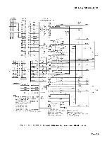
Page 16: ...OCK EQUIPMENT END SEE PARA 3 03 _ J 46 _I _ 1 21_ 25 t NOTE 2 2 IF THE POWER UNIT IS TO BE CONNECTED AT t I THE 149B ADAPTER OR THE 66E3 25 BLOCK I I D STATION INSULATE AND STORE THE BL V PAIR AT THE I I 95B TYPEI KEY EQUIPMENT END LI WIRE POWER L L117 VAC 3 INSULATEAND STORE THE BL V AND V BL UNIT NOTES MOUNTING CORD LEADS FROM PSB TERMINALS I AND 4 4 A 95B TYPE POWER UNIT IS REQUIRED FOR EACH TE...

Page 17: ... BL 16 Kit LK BL R 17 of Parts SHi G W 18 PrR BL V 20 VDD W G 21 M1 S BK 4 7 P1 BL R 13 8 666B 15V BK S 14 16 TRMTR S O BK 3 18 T7A Cord A1 Y O 29 19 F1 i G Y 2 17 LK BK O 11 35 760A LSPK SP1 G 34 20 R2FK Cord SP2 R 335 295 3B 95B Type AC1 _ Pwr Unit AC2 4B 2012B MD or AC1 27 27 2012D Trnsf AC2 36 36 Insulated and stored t Terminal on network 5 To reduce loudspeaker volume move SP2 lead to termina...

Page 18: ...holes in the chassis before the screw is refastened Failure to do this will result in improper seating 3 20 To remove the handset cradle from the of the faceplate housing proceed as follows 1 Remove the faceplate paragraph 3 19 and place the handset aside E LineKey Removal 2 Remove upper housing if provided paragraph 3 18 To remove use the following procedure 3 21 b 1 Remove faceplate paragraph 3 ...

Page 19: ...the directory sheet and faceplate jack are against the two tabs on the chassis Misalignment may cause the bottom of the 4 Depress the RECORD button The RECORD housing to bow lamp adjacent to the RECORD button will light A number can be called and recorded 8 When replacing the housing keep the simultaneously by lifting handset before depressing handset jack from being trapped between the RECORD but...

Page 20: ...180818 Kit of Parts switch must be in the OFF Kit of Parts and dial intermix feature is position provided LAST NUMBER DIALED feature is functional only when the feature switch is 5 02 Whenever a new number is recorded in a in the OFF position previously used memory position it will automatically replace the previously stored number 5 06 Operation of LAST NUMBER DIALED feature C Delete A Number Fro...

Page 21: ... to be rerecorded DIALED button c For sets equipped with the one touch A Trouble Analysis calling option with speakerphone and dial tone detector simply depress the 6 02 When trouble is encountered the subsequent LAST NUMBER DIALED button procedure should be followed F End to End Signaling 1 Confirm improper operation either as a basic telephone set or as an automatic dialer 5 07 For end to end si...

Page 22: ...ower 7 When battery has been connected at least results in the loss of stored numbersAI five minutes check memory retention by momentarily disconnecting ac power and then 2 Proceed per paragraph 3 17 automatically dialing a known telephone number 3 Loosen the four captive mounting screws of the memory Fig 4 C Memory 4 Gently raise the left side of the memory and rotate to position shown in Fig 5 T...

Page 23: ...rs 0 9 Test for operation of the logic reset switch 2 Remove the faceplate paragraph 3 19 and paragraph 3 07 7 place handset aside 10 Reprogram memory see Part 5 0 3 Remove upper housing if provided paragraph 3 21 b F Ringer 4 Remove the cradle paragraph 3 20 6 07 To replace 5 Remove the buzzer mounting screw 1 BDisconnect power unit from ac outlet and unplug battery 6 Remove the mounting screw an...

Page 24: ... mounting screw 13 Reprogram memory see Part 5 9 SRoute leads through wire guide as shown in Fig 3 10 Reconnect battery and power unit J Faceplate 11 Reprogram memory see Part 5 e 6 11 To replace a 2872A1 87 faceplate with a 2872B1 faceplate 1 Remove the 2872A1 87 faceplate by lifting I Handset up at any of its edges 6 10 A defective G15A handset may be replaced 2 Remove the four captive housing s...

Page 25: ...1 K Speakerphone 6 13 For speakerphone connections use appropriate Tables B through E 6 12 For maintenance information on the 3B MD I or 4A speakerphone systems refer to Section 512 620 100 or 512 700 100 respectively Page 25 ...

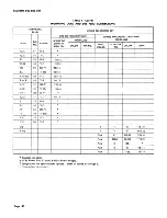
Page 26: ...OTE 2 CORD TO PSB DESIG COLOR FROM TERM 55A 55B TERM T1 V G 2 19 1 8A R1 G V 11 28 10 7A A1 12 2 A1 AG V S L2_ 5 11 12A LK S V 17 11 35 llA SPO O V 34 3 18 5B R or R1 18 34 1B Tel Set R or R1 9 25 1A B or B1 17 33 2B B or B1 8 24 2A Strap BK 10 Strap BK 20 Strap BK 19 i Strap BK 26 Strap BK 29 Input G R 2 PB O BK 9 Input G R 11 D 180493 Kit LK Y G 17 of Parts DT O Y 19 VDD R O 21 DR Y O 24 Page 26...

Page 27: ... CORD TO PSB DESIG COLOR FROM TERM 55A 55B TERM DTT BL Y 26 SPR Y BL 27 D 180493 Kit COM BK O 29 of Parts SPO G Y 34 Contd S 28 Switch S 29 CE BL BK 10 B BK BL 15 D 180492 SHa R BL 16 Kit of LK BL R 17 Parts SHi G W 18 PFR BL V 20 VDD W G 21 M1 S BK 4 7 P1 BL R 13 8 15V BK S 11 16 666B MD S O BK 3 18 TRMTR T7A Cord A1 Y O 29 19 F1 G Y 2 17 LK BK O 11 35 760A MD SP1 G 34 20 Lspk R2FKCord SP2 R 335 ...

Page 28: ...I I I I I I 1 I II II I 95B Type AC1 _ 3B Pwr Unit I I _ AC2 i 4B I 2012B MD AC1 _ 27 27 or 2012D Trnsf AC2 36 36 Note 1 Plug telephone set mounting cord into 149B adapter Note 2 When 55A control unit is used it must be the type modified for TOUCH TONE and strap terminals 20 and 21 55A or 4 and 5 55B Insulated and stored t Terminal on network To reduce loudspeaker volume move SP2 lead to terminal ...

Page 29: ...K PSB 20 CE BL BK 10 B BK BL 15 D 180492 SHa R BL 16 Kit LK BL R 17 of Parts SHi G W 18 PFR BL V 20 vDD w Q 21 BR V 85B1 AC1 BK AC1 Power Unit V BR AC2 Y AC2 BL V 95B Type AC1 R 21 I Powe r Unit V BL i AC2 G 46 i Note 1 Plug mounting eords of telephone set 108 type loudspeaker and 680 type transmitter into 82B eonneeting block Install option plug in ringer cutoff mode Note 2 For 1A1 or 1A2 KTS eon...

Page 30: ...UIP NOTE 1 DESIG COLOR FROM TO PSB COLOR TO TERM T1 V G 2 R1 G V 11 A1 Note 2 AG V S L2t LK S V 17 Tel Set SPO O V 34 Strap O V 10 to 35 Strap BK 10 Strap BK 20 Strap BK 19 Strap BK 26 Strap BK 29 Input G R 2 PB O BK 9 Input G R 11 LK Y G 17 DT O Y 19 D 180493 Kit VDD R O 21 of Parts DR Y O 24 PL O R 25 DTT BL Y 26 SPR Y BL 27 COM BK O 29 SPO G Y 34 S 28 SWITCH S 29 Page 30 ...

Page 31: ...it SHa R BL 16 of Parts LK BL R 17 SHi G W 18 PFR BL V 2O VDD W G 21 BR V 85B1 AC1 BK AC1 Power Unit V BR AC2 Y AC2 BL V 95B Type AC1 R 21 Power Unit V BL AC2 G 46 ii Note 1 Plug mounting cords of telephoae set 108 Type loudspeaker and 680 Type transmitter into 82B connecting block Install option plug in ringer cutoff mode Note 2 For 1A1 or 1A2 KTS connect link between 2 and A1 For 1A KTS connect ...

Page 32: ... R 2 PB O BK 9 Input G R 11 LK Y G 19 DT O Y VDD R O 21 D 180493 Kit DR Y O 24 of PL O R 2_ Parts DTT BL Y 26 SPR Y BL iii COM BK O 29 SPO G Y Switch S S Note May be used for applications where first dial tone is not precise 350 Hz and 440 Hz but all subsequent dial tones must be precise if number is to be dialed automatically Insulated and stored t Switch is not required when speakerphone is not ...

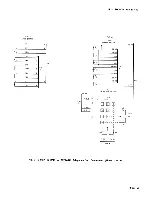
Page 33: ...W BR _ i I 24 _ Y O _ DR I CD O R PL DR W J _ 25 26 BL Y __ DTT BATTERY Y BL _ SPR 1 P o _1 B Y STRAP S _ I l BK I 3 x_l BK BK I l 3 BK NOTE 5 W LRS I BK 2 BK O Q COM FIG E B R _ a _ B R S i J BL V NOTES V BL I FOR 3B SPEAKERPHoNE WITH 149B ADAPTER MB7 G Y RELAY OR 4A WITH 82B CONNECTING BLOCK USE O V LEAD FOR 4A DR W SPEAKERPHoNE WITH 82A MD CONNECTING Y G W BR BLOCK LEAD WILL BE V BR 2 FOR 28 2A...

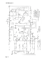
Page 34: ...ELAY PRINTED WIRING BOARD D 80492 INPUT G R FIG DT O Y PFR BL V _o7 I B VDD W G __ _4 VDD R O DR Y O PL O R FIG E DTT BE Y ONE TOUCH SPR Y BE CALLING SWITC H P O D 180493 lS_ s ol FIG _S B 2 S COM BK O I SPO G Y Fig 9 2872AIM MD or 2872A2M Telephone Set Connections Sheet 2 of 5 Page 34 ...

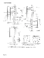
Page 35: ... b G W BR c R G d G d R 10 e W e BL FIIG f R f W BL FIG g BK g JFiG H C A W B h BL h V BL i C BL E S R 0 j BR W FIG I c D A O W 0 k DIAL FREQUENCY SWITCHES I Y G FIG FIG B I BR _ H2 J w o L HI H3 Y BR Y O FIG A Fig 9 2872AIM MD or 2872A2M Telephone Set Connections Sheet 3 of 5 Page 35 ...

Page 36: ...L______ b Y _ _ PIB RINGER BK 13 S Y FIG J FIG BL W _ o _ TYP_ _TWO F i FIG J _2__E 15 G j 0 16 O Y kl _ FIG I FIG K K _ Y S _ T 2v v o F _ PHYSICAL TERMINAL LAYOUT PHYSICAL TERMINAL LAYOUT OF 425K NETWORK OF 4 _ _8 TYPE NETWORK A BL W __ 2 _t _ _ T F A 2 Z K RR R G I _C S 2 _ _ F _ _S _ _ _ RR Lira ON _ _Z K _ C 2__ g R _ BK 1 B __ T LI 2 _ G GN BK G FIG B 2 G __ _ RR G BK _ B GN I V BL S R _ _ L...

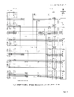
Page 37: ...W S W S O_ I I 7 R o2 _ 1_ 29 T2 W BR W BR _ 3 I 2 o _ 17 sPARE _ Y_ __ _ _ 42 _ S PARE Y O i _ 5 I R2 BR W i BR W _6 C _ 4 _ i i FIG J FIG B FIG I GREEN 9 L3 BR R BR R _L _____ LG3 R BR R BR LG_ _ 34 3AI3H R G I S W _ _ 33 x BK _ 2 32 T3 R O _ R O _ 3 1_ 3 AC PWR BL V _ _ __ _ _ 1 AC PWR V BL 05 J 7 R3 O R O R o6 C_ _i _ __ BROWN _ 12 L4 O BK O BK oIL 36 4A 4H BK BL BR I _ r Y 02 _11_ 4 T4 R S R ...

Page 38: ...B1 4 Key HPPPPS TB1 3 TB1 2 TB1 2 TB1 2 TB1 5 TB1 4 Functions t HPPPSS TB1 3 TB1 2 TB1 2 TB1 5 TB1 5 TB1 4 HPPSSS TB1 3 TB1 2 TB1 5 TB1 5 TB1 5 TB1 4 COMMON SIGNALING SEE NOTE COLOR BLUE ORANGE GREEN BROWN SLATE 508 PLUG PIN NO 2 2 2 2 2 1 LEAr COLOR W R BK Y V S HPPP P S TB1 3 TB1 3 TB1 2 TB1 2 TB1 2 TB1 3 Key Functions HPP P P S TB1 3 TB1 2 TB1 2 TB1 2 TB1 2 TB1 3 Note Insulate and store BK stra...

Page 39: ...BL 1 BL 1 W O L 1 3 G W B L L LG 1 28 W G BL LG R 2 4 BR W O 6 T 2 29 W BR O 3 B 2 5 S W O 2 R TB1 2 A 2 30 W S O 1 L 2 6 BL R O L LG 2 31 R BL O LG R 3 7 O R G 6 T 3 32 R O G 3 B 3 8 G R G 2 BK TB1 2 A 3 33 R G TB1 7 G 1 S W TB1 7 L 3 9 BR R G L LG 3 34 R BR G LG R 4 10 S R BR 6 T 4 35 R S BR 3 B 4 11 BL BK BR 2 Y TB1 2 A 4 36 BK BL TB1 9 BR 1 BR TB1 9 L 4 12 O BK BR L LG 4 37 BK O BR LG R 5 13 G...

Page 40: ... 4 3 Y G PS B 3 _ SG 19 BR Y TB1 5 BL 44 Y BR TB1 6 R or R1 20 S Y TBI 13 B or B1 45 Y S Net K AC1 21_ BL V PSB 30 AC2 46_ V BL PSB 31 SPO 22 _ O V St arc 47 V O Net T Rl 23 G V TI i 48 V G IR 24 BR V IT i 49 V BR LK 25 S V A 50 V S Tip S 4 G TB1 8 Ring S 5 R PSB 12 Pink HL BR W PSB 32 I Pink HLG W BR PSB 33 _ Pink 3 BL Pink 2 G TBI 1 Pink 1 Y BL TB1 3 Insulate and store t 95B1 Power Unit Touch A ...

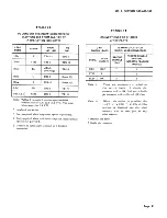
Page 41: ... PSB 12 Spare 1 Note 1 These are connectors attached to i LSct BR TBI 1 TB 6 the switch leads A single pin connector with a BK lead and a double Net L2 j R BL TBI 1 TB1 6 pin connector with a R and BK lead Note Tables B through E provide speakerphone Note 2 When this option is provided the connections for 1A1 and 1A2KTS The same LAST NUMBER DIALED LND tables apply forlAKTS feature is disabled and ...

Page 42: ...KEY SERVICE LEAD CONNECT LEAD CONNECT DESIG COLOR FROM TO DESIG COLOR FROM TO Tip W BL 1PU 3 TB1 8 Tip W BL 1PU 3 Net K Ring BL W 1PU 6 TBl 16 Ring BL W 1PU 6 TBI 13 B1 Y S Net K B1 Y S Net K I Strap BK Net K _ _ B 35 R1 S Y TBI 13 R1 S Y TBI 13 Insulated and stored Strap BK TBI 13 TBl 16 A Lead W O 1PU 1 TBI 1 Hold Y BL TB1 3 LRS 2 BR PSB 14 Insulated and stored Page 42 ...

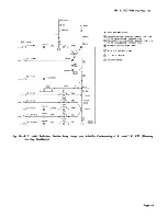
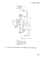
Page 43: ...STATION BUSY LAMP Lo _ T_ O WITH STATION BUSY LAMP S G I HOLD OPTION BL Y BR T81 6_ 44 _ FACTORYWIRING _ CR _ 533F TBI IO _ G SP V O T NETWORK _ 47 Q Z _ eL 3 H _LD ST Y B IA W O IPU 2 w 27 v IBi 2ND _ U R SIRAP I 21 30 2A W S EK 3RD 33 3A R G TBI 7 S W I PvU 2 BK e _ IBI 4TH 4A BK BL TBI 9 BR I PU 2 Y _ 36 G 5TH V_ 5A BK BR rBI 4 5 I PU 2 V _ _39 2 X m Fig IO D I Hold Exclusion Station Busy Lamp ...

Page 44: ..._ J TYPE lJ J lCONTROL I IOR 2012D I POWERI _ I uNIT I INSIDE WIRE DIOR CORD TRNSF l lit VAC IW OR CAE4 E MOUNT I NG CORD A25B CABLE 117VAC TO KEY TELEPHONESYSTEM SEE NOTE NOTE DISCONNECT THE V BL AND BL V LEADS IN THE CABLE AT KEY SYSTEM END Fig l l 0BIock Diagram 2872A1M MD or 2872A2M Telephone Set Using 3B MD Speakerphone Page 44 ...

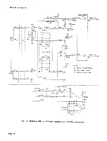
Page 45: ...CTING __J BLOCK ___ 1 D8S 87 I r o 1 j _o o I TYPE _ I A25B CABLE TO KEY TELEPHONE SYSTEM NOTE 2 NOTES 1 STRAP NECESSARY ONLY IF SET IS ALSO EQUIPPED WITH DIAL TONE DETECTOR TO PROVIDE ONE TOUCH CALLING OPTION 2 IF POWER IS PROVIDED THROUGH KEY CABLE USE BR V PAIR FOR 85 TYPE POWER UNIT AND STRAP 24 TO ACt AND 49 TO AC2 ON 82B CONNECTING BLOCK Fig 12 Block Diagram 2872AIM MD or 2872A2M Telephone S...

Page 46: ... I C B _ _ _ 49 I I BL Y 34 V BR Ii I I I _ I I I FW4 I I I I J I I R BR I I I I 3 8 LEGEND y __ ___B_I _ _ _ __ WITHOUT 4 WIRE OPTION I I TB2 WITH WIRE OPTION t R 1 I I t R 12 BR Y I G BK _ I _ _ W INSULATE AND STORE TRM_TRI il R I I 1 BK 1 1 BK _8 Y BL _ TB2 4 WIRE CONTROL NET NET MTG CORD TBI l YJ _ L_ 3 2 AI O w _ Y T C BR _TB O _ I HOLD X e i b I 2 I Y BL 27 IA W O I I v V_ 2 W _ TBI I _ 2 R ...

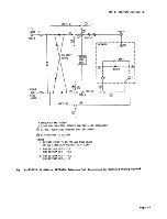
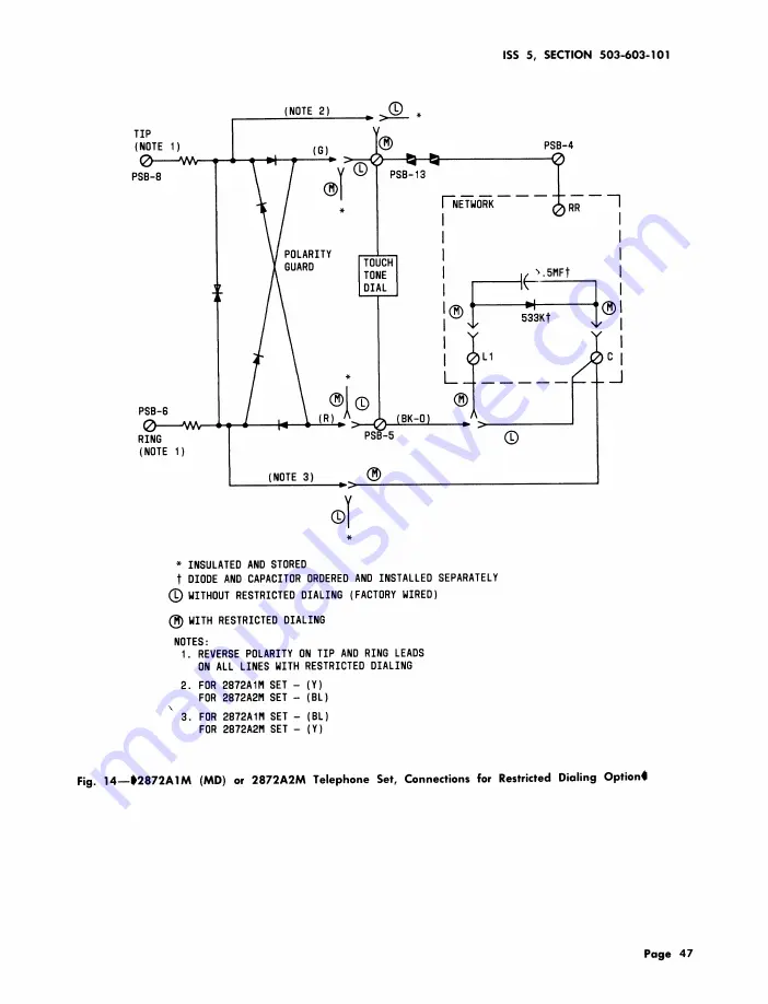
Page 47: ...D AND STORED t DIODE AND CAPACITOR ORDEREDAND INSTALLED SEPARATELY _WITHOUT RESTRICTED DIALING FACTORY WIRED _WITH RESTRICTED DIALING NOTES I REVERSE POLARITY ON TIP AND RING LEADS ON ALL LINES WITH RESTRICTED DIALING 2 FOR 2872AIM SET Y FOR 2872A2M SET BL 3 FOR 2872AIM SET BL FOR 2872A2M SET Y Fig 14 1_2872A1M MD or 2872A2M Telephone Set Connections for Restricted Dialing Option4 Page 47 ...

Page 48: ...03 101 h n _ _ _ s _ 1 _ 5 _ _ o _ _ _ 1 _ l 0 m _ 4 _ _ o 0 _ _ _o _ _ o 1 _ _ __ L Uw _ 2 I_ _ T _ 17 V _ S _ __1I _ _ _ s Y o o 1 _ 1_ i i _ o It o __ _ J I l _ _ _ _ _ _ _ _ _ o i 0 i _ _ v I__ _ 1 vii _ Page 48 ...

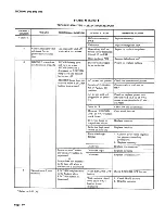
Page 49: ...andset or jack in telephone set Dial tone present but 12 pin connector 1 Check connector insertion sidetone absent No or dial not 2 Replace dial audible TOUCH TONE properly inserted signal on pins on power supply board Defective 616B jack Replace 616B jack Defective network Replace telephone set 3 Cannot manually dial Clicking sounds or Bridged set off hook Place bridged set on hook when off hook ...

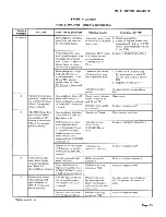
Page 50: ...818 Change switch position to Kit of Parts in ON OFF position AC power unit not Check or replace power unit plugged in or defec should read 13 4 to 18 VAC tive across screw terminals 30 and 31 on PSB Open in IW Check IW and connection Memory RECORD Clear stuck button OFF or WAIT button stuck down Defective lamp or Replace memory lamp driver circuit Defective logic reset Replace line key switch on ...

Page 51: ...rong number is dialed from memory 9 Cannot dial properly Did not record 1 Record per 5 01 from memory properly 2 See No 7 MB7 relay does not Battery not plugged Plug battery in operate no clicking in 2872A2M tel sound heard when set memory button is Memory not securely Tighten memory mounting depressed No audi mounted screws ble TOUCH TONE signal present Open circuit in Check for proper strap lead...

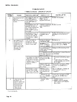
Page 52: ...ctive cir pausing momentarily cult components at the wait space Defective dial tone Replace dial tone detector PWB on a train of recorded detector assembly of D 18049_3 Kit of Parts digits if option is provided 10 Cannot manually dial With a strap lead Defective circuit or 1 Check connections per Table off hook for ac between screw terminals connections on B C D or E power failure condi 10 and 15 ...

Page 53: ...OFF button is phone option released Defective line switch Replace telephone set a b contacts 13 RECORD lamp does Speakerphone indicator Handset off hook Place handset on hook not turn off when lamp does not turn on speakerphone ON Line lamp is lit button is depressed With temporary strap LK relay circuit Replace D 180492 Kit of Parts Wired for speaker lead added between defective on phone option s...

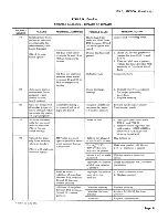
Page 54: ...ssed in the auto connected to PSB 34 matic dialing mode Wired for one 4A speakerphone in Ch xnge to 82B connecting block touch option stalled using 82A con necting block 4A speakerphone with Add strap from terminal 10 to 35 82B block strap not in 82B block placed on 82B block With temporary strap be One touch calling 1 Turn one touch calling switch tween screw terminals switch turned off or on 28 ...

Page 55: ...ated before all sequence between from handset cradle taken off hook while digits are dialed a b and h i contacts automatically dialing on a speakerphone 22 Set dials automati Noise on line 1 Add 5pf capacitor between cally but does not PSB 21 and PSB 26 wait for dial tone 2 Remove above capacitor and Wired for one add resistor 10K_ 50K_ in touch calling series with G R dial tone detector input lea...

Page 56: ...2M TROUBLE NUMBER FAILURE ADDITIONAL SYMPTOM POSSIBLE CAUSE REMEDIAL ACTION 24 Hum or Noise Unbalanced Check for unintentional caused by electrical telephone line connections that might apparatus light cause an unbalanced dimmer switch etc telephone line Page 56 56 Pages ...

Reviews: