background image

BELL  SYSTEM  PRACTICES 

AT& TCo  Standard 

SECTION  502-61 2-410 

Issue  4,  March  1975 

SERVICE 

2636CA  AND  2637DA TELEPHONE  SETS 

1. 

GENERAL 

1.01 

This section contains connection and  maintenance 
information for 2636CA (18-button)  and 2637DA 

(30-button)  CALL  DIRECTOR®  telephone  sets 
equipped  with  headset  jacks. 

1.02 

This  section  is  reissued  to: 

• 

Change  contact  strip  assembly  840151947  to 
840151047,  2.02 

• 

Add  information  on  D-180463  Kit  of  Parts, 

2.08  and  Fig.  3 

• 

Revise  2.05 

2. 

CONNECTIONS 

2.01 

These  sets  are  factory-wired  for  use  with 

1A1,  1A2,  or  6A  KTS  line  circuits.  They 

may  also  be  used  with  1A  KTS  line  circuits  by 
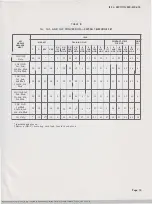
modifying  the  set  as  shown  in  Tables  A  and  B. 

Line  circuits  for  1A,  1A1,  or  1A2  KTS  may  be 

connected  to  the  same  set  under  the  following 
conditions: 

(a)  1A1  or  1A2  KTS  lines  must  be  connected 

to  the first key  units  with  1A  lines connected 

to  supplementary  key  modules. 

(b)  1A,  1A1,  or  1A2  KTS  lines  should  not  be 

connected  to  the  same  6  line  key  module. 

(c)  1A,  1A1,  or  1A2  KTS  lines  appearing  behind 

a  m a n u a l   s w i t c h b o a r d   s h o u ld  n o t   b e  

intermixed  o n  a  CALL  DIRECTOR  telephone  set 

due  to  the  different  time  out  intervals  provided 
by  the  associated KTU's. 

2.02 

These sets  are  equipped  with a  635A5C  (5-line 

pickup  and hold)  or  a  635AD5C  (4·\ine  pickup, 

cutoff,  and  hold)  key  in  the  first  module  position. 
Contact  strip  assemblies  [required with sets  equipped 
with  a  D120K  (MD)  or  D200S  (MD)  mounting  cord] 
differ  between  the  two  keys.  If  ordered  for  field 
replacement,  the  635AD5C  key  is  furnished  with  a 

piggy-back  adapter  to  which  the  slate  mounting 
cord  plug  is  connected.  The  necessary  contact strip 
assemblies  (840151039  and  •840151047•  )  will  be 
shipped  with  the  635AD5C  key,  and  will  replace 
the  840151120  and  840151138  assemblies  supplied 
with  the  635A5C  key. 

2.03 

Because  of  the  physical  arrangement  of  the 

635-type  key,  the  contact  strips do not extend 

to  the  chaining  switch.  This  requires  a  second  tip 

and  ring  conductor  to  each  module  (except  the 

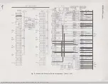
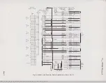
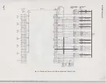
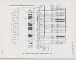
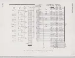
last).  See  Fig.  2,  sheets  1  through  5. 

2.04 

The  line  conductors  of  the  mounting  cords 

for  these  sets  terminate  in  individual  plugs 

on  a  per  line  basis  and  are  connected  to  the  rear 
of  the  keys.  This  permits  rearrangement  of  line 
appearances either in  the  set  or at the  key  equipment 
distribution  point.  Current  production  sets  are 

equipped  with  a  satin-silver  (-87)  mounting  cord. 

2.05 

All  line  pickup  key  positions  are  convertible 

to signaling or common signaling arrangements 

by  removing  the  P-28E773  screw  detail  from  key 

positions involved  and  making  the necessary wiring 

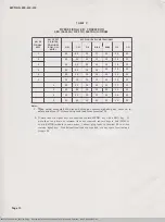
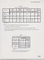
changes  per  Table  C. 

2.06 

These  sets  are  not  intended  for  use  with 

3-type speakerphone  systems. 

2.07 

The  2636CA  and  2637DA  telephone  sets  are 

factory  equipped  with  a  KS-20419L1  (10  volt 

AC  only)  buzzer. 

2.08 

When  station  busy  lamp  feature  is  required 

with  these  sets  having  1A1  or  1A2  KTS  line 

circuits,  there  are  two  optional  circuits  available. 
The  busy  lamp(s)  will  light  whenever  a  line  pickup 
button  is  depressed  and  the  handset  is  off-hook  or 
the  headset  is  plugged  into  the  jacks.  This  optional 
equipment  must  be  ordered  separately.  If  more 
than  one  busy  lamp  is  required,  a  6C  KTU  must 
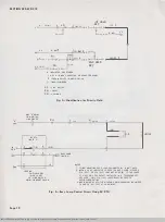
be  connected  as  shown  in  Fig.  5.  For  a  single 

busy lamp,  •install  a  D-180463 Kit of Parts (ordered 

separately),  consisting of a  P-90D033  Printed  Wiring 
Board Assembly  and  840361836  plug  assembly  (light 
beige)..  Connect  kit  of  parts  as  shown  in  Fig.  3. 

©  American  Telephone  and  Telegraph  Company, 

1975 

Printed  in  U.S.A. 

Page  1 

SSP 502-612-410-i04_1975-03-0l.jpg  Scanned by  Frank  Harrell,  {Cowboy  Frank) Castle  Rock, Colorado  Feb 04,2012  16:18:38 

Summary of Contents for 2636CA

Page 1: ...y and will replace the 840151120 and 840151138 assemblies supplied with the 635A5C key 2 03 Because of the physical arrangement of the 635 type key the contact strips do not extend to the chaining switch This requires a second tip and ring conductor to each module except the last See Fig 2 sheets 1 through 5 2 04 The line conductors of the mounting cords for these sets terminate in individual plug...

Page 2: ...5C key from kit of parts 3 Reterminate contact strip leads and connect mounting cord plugs with the exception of the white plug which is insulated and stored Note Contact strips are not required with sets equipped with Dl20M or D200AA mounting cords 4 Rearrange wiring per Fig 4 Hold key in first module is used as regular hold and if required I Hold Second hold key is used for Priority Hold 2 10 Wh...

Page 3: ...2ND 1ST 2ND 1ST 2ND 3RD y MOD MOD MOD MOD MOD MOD MOD 1A1 1A2 10 10 5 15 9 11 9 11 21 8 Only 1Al 1A2 1st 2nd Mod 10 35 21 40 5 35 9 11 9 11 40 8 1A 3rd Mod 1A1 1A2 1st Mod 10 35 11 40 35 15 9 40 9 40 21 8 1A 2nd 3rd Mod 1A Only 10 26 9 5 15 26 11 26 11 21 18 Insulated and stored Page 3 BSP 502 612 410 i04_1975 03 03 jpg Scanned by Frank Harrell Cowboy Frank Cast c Rock Colorado Feb 04 2012 16 19 2...

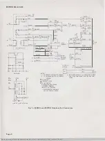
Page 4: ...l TO FIG 2 SH I B K t 2 SH2 I TO CONTACT STRIPS I ST MODULE 2 TO CHAINING SWITCH 1ST MODULE 3 NIA RINGER SHOWN TIA RINGER HAS SINGLE COIL 5200 OHMS AND ONLY I R AND IBK LEADS LEGEND FL fLASH KEY HS HEAOSET JACKS LS LINE SWITCH INSULATED AND STORED t ETWORK TERMINAL 1 AMPLifIER TERMINAL UNOESIGNATEO TERMINALS ARE ON TERMINAL BOARD Fig 1 2636CA and 2637DA Telephone Set Connections Page 4 BSP 502 612...

Page 5: ... THE 658A KEY IS REQUIRED AS A OUAL PURPOSE KEY REMOVE STRAP BETWEEN TERMINALS 17 AND 18 USE Ml 1 CORD OR EQUIVALENT TO CONNECT TERMINAL 17 TO A DISSIMILAR GROUND OR NONGROUNDED CIRCUIT 5 TO SUPPLY 1 HOLD FEATURE TERMINATE 0 Y MOUNTING CORD LEAD FROM FIRST MODULE ON TERMINAL 24 LEAD BECOMES SP LEAD AT EQUIPMENT 6 IF HOLD POSITION LAMP IS REQUIREO CONNECT G Y LAMP GROUND LEAD AND Y G LAMP LEAD TO G...

Page 6: ...W 31 W BL 26 L_ __________ o w 2 w o 27 G W W G 3 28 7 21 7 46 6 t II T I 7 23 7 48 m IT III T TO SH 4 _ Fig_ 2 Module and Connector Cable Arrangements Sheet I of 5 SSP 502 612 410 i04_1975 03 06 jpg Scanned by Frank Harrell Cowboy Frank Castle Rock Colorado Feb 04 2012 16 20 50 S Y Y Sl 5 l t j o Y Y O G Y tv l G BK BK G lBR BK 5 BK BR l S BKJ BK s S R R S BL BK BK BL f i 5 o R R 0 G R 5 R GI BR ...

Page 7: ... CABLE 0 W BINDER CONN 2 20 5 Y BZ 45 IY S BZI 44 1 1 SPARE P8 19 BL Y 16 41 Y Bl 17 o v 42 Y O A H S OR Sl IB G Y l OR 56 s f LG OR 512 7 5 BK G BR BK 39 BK BR A1H1S OR Sl 15 j l OR SS 40 LG OR Sit tO S R 35 R 5 BL BKj BK BL A H S OR Sl 36 0 BK l OR 54 12 BK 0 LG OR SID 37 7 O R 32 R 0 8 G R 33 R G A H1SOR Sl 9 BR R L OR 53 34 I R BR LG OR 59 4 BR W 29 W BR s s w 30 J A H SOR 51 6 l OR 52 31 R BL...

Page 8: ...0 BL R 6 R Bl 31 Bl W C RI BR Y SPARE Y BR SPARE s v SPARE I S l Se6Bt BL y R Y BL T H xl a y ol AHSORSI I L LG G BK R BI G T BR BK B t 11 A H SOR51 L BK S LG S R R R S T BL BK B fBK BLJ AIHISOR51 6 Bk L BK 0 LG o R R R O T lc Rl B R Gl A H SORS L LG BR w R W BR T s w B w s A H OR51 BL R L R BL LG BL W R W BL T o wj 8 1 A H SOR 51 L W G LG Fig 2 Module and Connector Cable Arrangements Sheet 3 of S...

Page 9: ... 0 37 5 O R R 0 BR R R BR BR 2 8 3 4 W BR Z9 t w BL R R BL BL W _iw eu w o G W 5 0 6 I 6 2 7 3 8 BR Y Y BR s v Y S BL Y t al 0 Y Y O G Yl Y G G BK tBK G BR BK BK BR S BK BK 5j 5 R R S BL BKj BK 0 O R l R G i BR W W BR 5 w ltl Sl BL R R BL BL W W BL O W w o G W W G SPARE SPARE SPARE SPARE R I B A H S OR 51 I CBSfi LG OR 512 R T B A H 5 OR 51 l OR 55 LG OR Sll R T B A H 5 OR 51 l OR 54 LG OR SID R I...

Page 10: ...S R R OR l 4 zn t Bl BK t BK a81KLll K l O R l G l 2 l1 36 81 Bll A H 5OfiSl O BK 51 0 Bl r z O BI L 54 OR UO LG BK 0 i BK 0 37 BK 01 LG SIO OR LGIO f 6 4 o 7 r o Lo l I STRAP I H R 0 32c OI T OR 2L G 3 g G A I S A H 5 OR S1 l lBR Rl l r j BR Rt j S 3 0 R L 19 LG R BRl 34 R BR LG 59ORLG9 f 76 f l BR WI 7 B Rc WLI __ R O R L 2 f s w W BRl 29 l OW Bo R l T OR LG 2 25 t 11 3 l w 5 J j t H s o Js l t ...

Page 11: ...BR LS Y 8 O W HS 0 BK I G V cs 6 5 51 A Y BR BL BUSY 44 LAMP NOTE WHEN A SINGLE BUSY LAMP IS REQUIRED EITHER THIS STATION BUSY LAMP CONTROL CIRCUIT OR THE BUSY LAMP CONTROL CIRCUIT WITH 6C KT U SHOWN IN FIG 5 MAY BE USED WHEN MORE THAN ONE BUSY L AMP IS REQUIREO ONLY THE 6C KT U BUSY LAMP CONTROL CIRCUIT SHOWN IN FIG 5 MAY BE USED Fig 3 tStation Busy Lamp Circuit using Printed Wiring Board Assembl...

Page 12: ...W 1______________ ___ GRD 1 I r I z J GRD b Page 12 LEGEND PU PICKUP KEY H HOLD KEY LS LINE SWITCH HSIA HEADSET JACK A L rBUSY LAMP NOTE 21 LG NOTES I Y BR MOUNTING CORD LEAD DESIGNATED BL IS NOT USED 2 WHEN A LAMP INDICATOR IS USED FOR BUSY LAMP EITHER A 51A IOV OR 52A 24V LAMP MAY BE USED IF THE LAMPS OF A KEY OR LAMP SOCKET INSTALLED IN A TELEPHONE SET ARE USED ONLY 51A IOV LAMPS SHALL BE USED ...

Page 13: ... 12 41 14 5 15 35 12 9 11 21 31 9 11 21 31 14 8 3rd 4th Mod 1A 5th Mod 1Al 1A2 1st 2nd 3rd Mod 10 12 31 14 5 15 12 45 9 11 21 14 9 11 21 14 41 8 1A 4th 5th Mod 1A1 1A2 1st 2nd Mod 10 12 21 14 5 12 35 45 9 11 14 31 9 11 14 31 41 8 1A 3rd 4th 5th Mod 1A1 1A2 1st Mod 1A 2nd 3rd 10 12 11 14 12 15 35 45 9 14 21 31 9 14 21 31 41 8 4th 5th Mod 1A Only 10 37t 13 5 15 35 45 37 11 21 31 37 11 21 31 41 18 In...

Page 14: ... 18 39 18 39 30 39 30 39 30 39 30 39 1 When using converted 6th pickup button as common signaling key remove in sulate and store Y 0 mounting cord lead from terminal 39 2 If more than six signal keys are required replace 635G5C key with a 658A key If more than five private or intercom lines are required convert keys in 2nd 2636CA or 4th 2637DA module in same order Connect plug leads to terminal 39...

Page 15: ...er circuit at equipment 3 To external ringer or buzzer Connect ringer or buzzer circuit to BL Y Y Bl connector cable leads at equipment 4 Connect T R and A leads from equipment and station to be cut off through contacts of auxiliary relay Connect battery to relay winding Use 227B or 421A KTU TABLE E P 900197 GUARD ASSEMBLY CONNECTIONS Note REMOVE FROM CONNECT TO WIRE OR LEAD COLOR GUARD NET ASSY N...

Reviews: