13
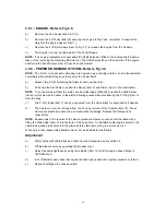
3.4 . - SYSTEM PRESSURE AND FLOW CHECKS.
1.
Connect a suitable hydraulic test unit to the powerpack. The unit should comprise a high
pressure flowmeter 0-50 l/min, a pressure gauge 0-200 Bar (0-3000 Psi), a temperature
gauge, and a load valve. Suggested unit available from UCC (UC 4120).
2.
Connect the test unit to the power pack with the load valve and the By-Pass lever in the by-
pass position and start the power pack. Allow the engine to warm up, set the by-pass lever to
the flow position. Close the load valve completely and check that the relief valve setting is
correct (140 Bar). The hydraulic oil will tend to get quite hot during this operation and
therefore the checking should be carried out as quickly as possible and the load valve
opened before excessive temperatures are reached.
3.
Carefully close the load valve to raise the pressure to 100 Bar (1500 Psi). Check that the flow
rate is between 27 and 30 l/min. Adjust the engine speed to give the correct flow.
DO NOT
EXCEED 3600 RPM " on load " speed.
If correct flow cannot be obtained within max engine
speed then the pump must be suspect; replace as necessary.
Summary of Contents for Major 30-140
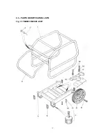
Page 22: ...22 4 3 PARTS IDENTIFICATION LISTS Fig 3 1 FRAME CHASSIS ASSY ...
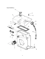
Page 24: ...24 Fig 3 2 Tank Assy ...
Page 26: ...26 Fig 3 3 Valve Block Assy ...
Page 28: ...28 Fig 3 4 Cooler Assy ...
Page 30: ...30 Fig 3 5 Pump Assy ...
Page 32: ...32 Fig 3 6 P O D Assy ...
Page 34: ...34 Fig 3 7 Hose Assy ...

