14
3.5. - REMOVAL AND REFITTING PROCEDURES.
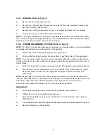
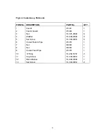
3.5.1. - FRAME/CHASSIS - Refer to Fig 3.1.
a)
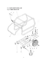
Remove the four Durlok Screws (Item 9) securing the frame to the chassis (Item 5) and retain
screws. The frame (Item 1) will now lift clear and the wheels are free to slide off their axles if
required.
b)
The rubber feet (Item 7) can be removed by undoing the Nut and Washer and withdrawing
the foot from its location.
c)
Removal of the Handle (Item 4) should only be carried out when the existing handle must be
replaced due to damage etc. The handle is riveted to the frame using a strong rivet (Item 2)
which is installed at the factory using a special tool. Replacement of these rivets cannot easily
be made without the special tool, and we recommend that this operation is carried out by the
Belle Group Willersey Service Department.
d)
The two Universal Mounting Plates (Item 12) can be removed by undoing the Set
Screws(Item 10) and Spring Washers (Item 11). Set Screws (Items 13 & 14) holding the
engine in place would be removed with the engine assy.
NOTE -
Reassembly of the Frame/Chassis components is the reverse of the above; it is strongly
recommended that new Spring Washers (Items 11 and 7) are fitted to ensure locking.
Summary of Contents for Major 30-140
Page 22: ...22 4 3 PARTS IDENTIFICATION LISTS Fig 3 1 FRAME CHASSIS ASSY ...
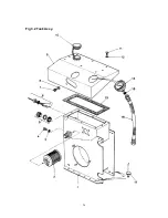
Page 24: ...24 Fig 3 2 Tank Assy ...
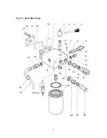
Page 26: ...26 Fig 3 3 Valve Block Assy ...
Page 28: ...28 Fig 3 4 Cooler Assy ...
Page 30: ...30 Fig 3 5 Pump Assy ...
Page 32: ...32 Fig 3 6 P O D Assy ...
Page 34: ...34 Fig 3 7 Hose Assy ...

