15
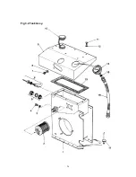
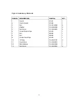
3.5.2. - COWL - Refer to Fig 3.2.
a)
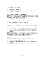
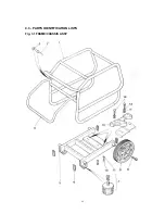
Remove the frame as described in 3.5.1. above.
b)
Drain the hydraulic oil by removing the Drain Plug (Item 4) and Seal (Item 3).
c)
Disconnect the Capillary Tube (Item 16) from the gauge end of the hose and plug to prevent
leakage.
d)
Remove the Cap Screw (Item 7) and Washer (Item 8) securing the Cowl to the Valve Block.
e)
Remove the 8 off Set Screws (Item 11) and Washers (Item 12) which secure the cowl to the
Tank.
f)
Lift away the Cowl from the hydraulic tank in an upward and forward motion to clear the
Q.R.C.Couplings (Fig 3.3. Items 17 & 18) taking care not to damage the gasket (Item 13).
g)
Access is now available to the inside of the tank, allowing removal of the Suction Strainer
Item 2), Float Switch (Item 6), and Sight Level Gauge (Item 5) for servicing.
NOTE
- It is recommended that a new Gasket (Item 13), drain plug seal (Item 3) and Gauge seal
(Item 15) be fitted upon reassembly.
NOTE -
The Tank (Item 1) should not normally require removal from the Chassis unless substantial
damage has occurred. If it is necessary to replace the Tank assy it should be note that the Rivets
(Item 17) used to secure the Tank are factory installed using a special tool and it is recommended
that this work be carried out by Belle Group Willersey Service Department.
Summary of Contents for Major 30-140
Page 22: ...22 4 3 PARTS IDENTIFICATION LISTS Fig 3 1 FRAME CHASSIS ASSY ...
Page 24: ...24 Fig 3 2 Tank Assy ...
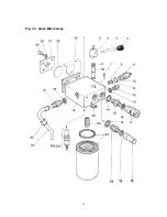
Page 26: ...26 Fig 3 3 Valve Block Assy ...
Page 28: ...28 Fig 3 4 Cooler Assy ...
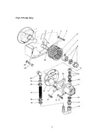
Page 30: ...30 Fig 3 5 Pump Assy ...
Page 32: ...32 Fig 3 6 P O D Assy ...
Page 34: ...34 Fig 3 7 Hose Assy ...

