16
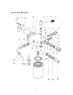
3.5.3. - VALVE BLOCK - Refer to Fig 3.3.
a)
Remove the Cowl as described in 3.5.2. above.
b)
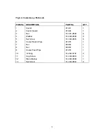
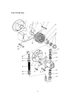
Disconnect the cooler feed and return pipes by undoing the swivel nuts at the cooler
connections (Item 7 & 8 Fig 3.4) and the Cap Screw and washer (Items 11 & 12 Fig 3.4).
Gently remove the pipes from their locations in the Valve Block.
NOTE -
Support the hexagon fitting of the cooler using the correct size spanner to avoid twisting
damage to the cooler.
c)
Disconnect the H.P. Feed pipe (Item 19) by undoing the pipe end nuts and gently remove the
pipe.
d)
From within the hydraulic tank remove the four Set Screws (Item 25) and Washers (Item 26)
remembering to support the valve block weight. Remove the Clamping Plate (Item 27) and
break away the valve block from the tank wall and remove the Gasket (Item 30), taking care
not to leave the Blanking Plug (Item 28).
NOTE
- Should further disassembly of the Valve Block be required the following points should be
noted: -
1)
Always refit a new Filter Can (Item 24) remembering to smear the new seal with clean
hydraulic fluid. It is normally sufficient to tighten to a good hand tightness, however the Can
should be checked for tightness once the powerpack has been re-assembled and run to
warm up the hydraulic oil.
If hand tightness proves to be insufficient to seal the Filter Can, a strap wrench may be used
provided that the Can is not distorted.
2)
The Relief Valve (Item 11) is a cartridge unit, and should only be removed to examine the
seals fitted to the nose. If problems arise regarding pressure control, it is advisable to fit a
new Relief Valve.
3)
Should any hydraulic fittings and bonded seals be removed it is advisable to refit using new
seals after examining the fitting to ensure that there is no damage.
4)
The By-Pass spool (Item 1B) can be extracted by removing the lever/knob (Items 5 & 6) after
slackening the grub screw (Item 3) and then removing the Boss (Item 4) from the top of the
spool. The Circlip (Item 22) can then be removed from the other end. The spool should then
be removed by gently pushing from the Circlip end until the 'O' Ring is revealed, and after
removal of this ring the spool should be pushed right through the opposite way thus avoiding
seal damage.
Refitting the spool is the reverse of the above by fitting the bottom 'O' Ring and pushing the
spool through the block to reveal the second 'O' Ring groove. The second seal can then be
fitted and the spool pushed back to its correct position and secured by the Circlip and boss.
NOTE-
To refit the valve block, carry out the reverse of the above instructions taking care to fit a new
gasket (Item 29) and before bolting the valve block to the tank ensure that the blanking plug (Items
28) is correctly fitted into the housing in the block and also ensure that the spigot locates into its
location hole in the clamping plate.
Summary of Contents for Major 30-140
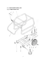
Page 22: ...22 4 3 PARTS IDENTIFICATION LISTS Fig 3 1 FRAME CHASSIS ASSY ...
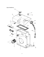
Page 24: ...24 Fig 3 2 Tank Assy ...
Page 26: ...26 Fig 3 3 Valve Block Assy ...
Page 28: ...28 Fig 3 4 Cooler Assy ...
Page 30: ...30 Fig 3 5 Pump Assy ...
Page 32: ...32 Fig 3 6 P O D Assy ...
Page 34: ...34 Fig 3 7 Hose Assy ...


