17
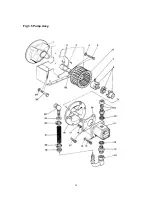
3.5.4. - COOLER - Refer to Fig 3.4.
a)
Remove the frame as described in 3.5.1. above.
b)
Remove the cowl as described in 3.5.2. above.
c)
Remove the two pipe connections at the cooler using two spanners (ie:- supporting the cooler
connection fitting against twisting and bending).
NOTE
- It may prove advisable to remove the pipes completely before attempting to extract the cooler
from its housing. Remember that the cooler and pipes will be full of hydraulic oil.
d)
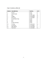
Unscrew the 6 off screws (Item 5) and 2 off Screws (Item 13) holding the cooler (Item 1) and
Guard (Item 2) to the fan housing, and retain the Nuts (Item 3) and Washers (Item 4).
e)
Gently pull the Cooler from its housing complete with Guard and separate.
NOTE
- Refitting the cooler assy is the reverse of the above, however it should be noted that the
cooler is manufactured from soft materials and should therefore be treated carefully to avoid damage.
It is strongly recommended that new Shakeproof Washers (Item 14) are fitted on reassembly and that
the 2 off Set Screws (Item 13) are loctited into position using Nutlock or similar strength product.
Summary of Contents for Major 30-140
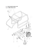
Page 22: ...22 4 3 PARTS IDENTIFICATION LISTS Fig 3 1 FRAME CHASSIS ASSY ...
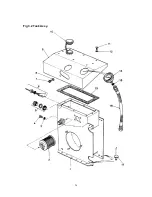
Page 24: ...24 Fig 3 2 Tank Assy ...
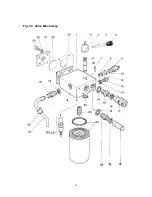
Page 26: ...26 Fig 3 3 Valve Block Assy ...
Page 28: ...28 Fig 3 4 Cooler Assy ...
Page 30: ...30 Fig 3 5 Pump Assy ...
Page 32: ...32 Fig 3 6 P O D Assy ...
Page 34: ...34 Fig 3 7 Hose Assy ...


