36
SECTION 5. -
CODES OF PRACTISE HYDRAULIC
POWER SYSTEMS
Before starting
Refer to Manufactures operating instructions.
Compatibility
Hydraulic power systems are designed to operate at a specific Flow and Pressure.
Equipment produced by EHTMA members carries a triangular colour coded range
identification label.
Check that both the tool and power unit have the same identification label before
operation.
It is imperative that power systems and tools having different colour codings are not
interconnected as this practise is both inefficient and Dangerous.
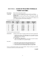
For reference the EHTMA colour is as follows:
Classification
Colour
Code
Nominal
Flow
l/min.
Flow
Range
l/min.
Nominal
Pressure
Bar.
Relief Valve
Pressure
Bar.
A
B
C
D
E
F
G
Z
Yellow
Blue
Green
Brown
Red
Black
Orange
Grey
6
15
20
30
40
50
60
10
5.5-6.5
13.5-16.5
18.0-22.0
27.0-33.0
36.0-44.0
45.0-55.0
55.0-66.0
9.0-11.0
135
129
103
103
103
103
103
135
180
172
138
138
138
138
138
180
If in doubt consult the equipment manufacturer
Characteristics
Operators not familiar with use of hydraulic power packs should note the following points:
1. Hydraulic power units use oil to transmit power, hence it is essential to only use
hydraulic oil of the type and grade recommended by the manufacturer. Also ensure
that the correct oil level is maintained.
DO NOT OVER FILL.
2. Use only clean oil and filing equipment.
3. Power units require a free flow of air for cooling purposes and should therefore be
sited in a well-ventilated area free from hazardous fumes.
Safety Points
1. Safety clothing etc, appropriate to the tool being used should always be worn.
2. Ensure their couplings are clean and correctly engaged before operation.
3. Check that guards to moving parts and hot areas are secure and undamaged.
4. Check hoses for deep cuts or exposed braiding; replace any damaged hose.
This code of practise applies to hydraulic power systems generally. Please ensure that you have read and
understand the manufacturer’s instruction before operating.
Aug 2002
Summary of Contents for Major 30-140
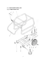
Page 22: ...22 4 3 PARTS IDENTIFICATION LISTS Fig 3 1 FRAME CHASSIS ASSY ...
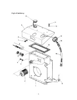
Page 24: ...24 Fig 3 2 Tank Assy ...
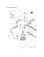
Page 26: ...26 Fig 3 3 Valve Block Assy ...
Page 28: ...28 Fig 3 4 Cooler Assy ...
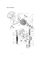
Page 30: ...30 Fig 3 5 Pump Assy ...
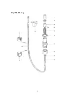
Page 32: ...32 Fig 3 6 P O D Assy ...
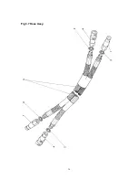
Page 34: ...34 Fig 3 7 Hose Assy ...

