Installing Your Cooker
Connecting to the gas supply
#
The inlet to the appliance is ISO 7 - Rp
1
⁄2
” internal
thread situated towards the top right corner of the
rear.
#
Fit the bayonet connection. This should be located so
as to ensure that the flexible hose does not kink.
#
Use a 900mm - 1125mm length of flexible hose.
#
Ensure that all pipe work is of the correct rating for
size and temperature.
Natural Gas
- Flexible connections should comply with
BS 669. Parts of the appliance likely to come into contact
with a flexible connector have a temperature of less than
70˙C.
LP Gas
- For flexible connections use a bayonet type
hose, suitable for use on LP Gas up to 50mbar pressure
and 70˙C temperature rise. The flexible hose should be
coloured black with a red stripe, band or label. If in
doubt, contact your supplier.
The appliance is designed not to project in front of
standard 600mm work tops.
To achieve best fit the cooker must be pushed against the
wall.
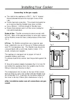
If the wall mounted adaptor backplate (fig 1) is to be fit-
ted behind the appliance then the suitable area for this
fitting is shown as the area on fig 2.
The temperature rise of areas at the rear of the cooker,
that are likely to come into contact with the flexible hose
do not exceed 70˙C. However, do not allow contact of
the hose in the top 150mm (the shaded area in fig 3).
After installation make sure all connections are gas
sound.
Fig 1
Fig 2
Fig 3
Summary of Contents for 100 GT
Page 1: ...Belling 100 110 GT...

