5
.
Parts replacement
5.1 Head
Arm
Holding
String
Arm
Collar
1. Turn off the main power switch on the front panel of PHOT-X
II
.
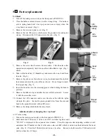
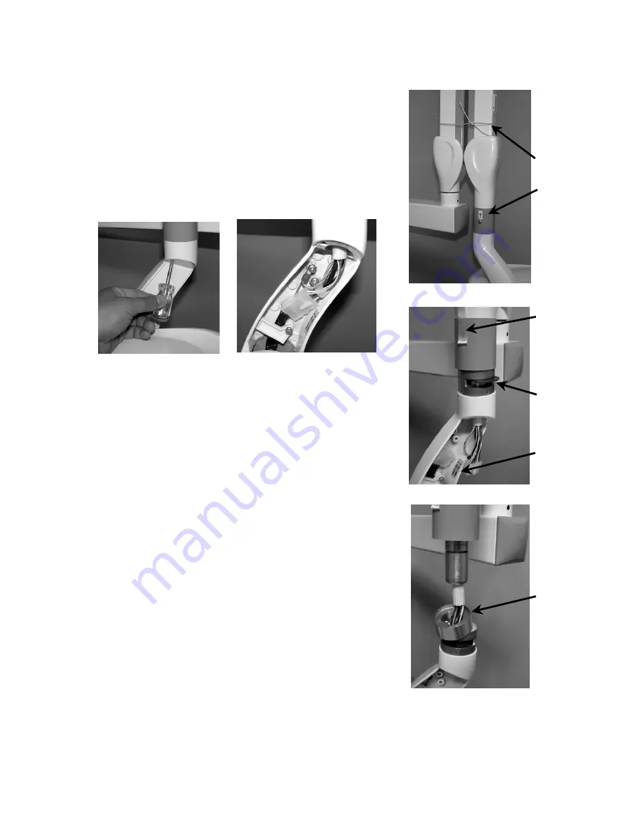
2. Close the balance arm and secure it with a strong string. The balance
arm is spring loaded and it can pop out and cause injury when the
x-ray head is removed. (Fig. 1)
3. Remove the screw and yoke cover. (Fig. 2)
4. Remove the two M5 screws which secure the ground wires and nylon
clamp. Disconnect the 10P connector in the yoke. (Fig. 3)
Fig. 1
Adhesive
tape
Head
Key
Fig. 2
Fig. 3
5. Remove the screw which secures the arm collar. Slide the arm collar
upward and temporarily hold it in position with adhesive tape. (Fig. 1
and 4)
6. Take out the head key (U shaped key) and remove the x-ray head from
the arm. (Fig. 4)
CP
value
label
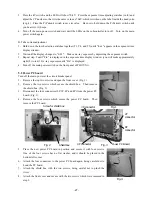
7. Remove the yoke cover from the new x-ray head and insert the shaft of
the balance arm into the yoke of the new head. Do not forget to insert
the stopper ring. (Fig. 5)
Fig. 4
8. Insert the head key into the retaining groove while holding the head in
position.
Stopper
Ring
9. Remove the adhesive tape and slide the arm collar downward. Secure
it with the arm collar screw.
10. Connect the 10P connector and secure the arm cable with the nylon
clamp in the yoke. Secure the green ground wires from the arm and
head to the ground terminal with an M5 screw.
11. Remove the string which holds the arm closed.
Adjustment after exchanging the x-ray head
A. CP value setting
1. Turn on the main power switch on the front panel of PHOT-X
II
.
Fig. 5
2. Hold down the P (Patient), C (Cone), and K.V. switches together until
“CP.-XX” is displayed in the exposure time window. Press the exposure time adjusting switches (
π
or
θ
)
and adjust the CP number so that it is the same value as 60kV, which is written on the label inside the head
yoke. (Fig. 4) Press the P (Patient) switch to save its value. Be sure to hold down the P (Patient) switch
until you hear two (2) beeps.
-26-


