3. Press the kV switch, and the LED will show 70 kV. Press the exposure time adjusting switches (
π
or
θ
) and
adjust the CP number so that it is the same value as 70kV, which is written on the label inside the head yoke.
(Fig. 4) Press the P (Patient) switch to save its value. Be sure to hold down the P (Patient) switch until
you hear two (2) beeps.
4. Turn off the main power switch and wait until the LEDs on the subcontroller turn off. Turn on the main
power switch again.
B. Tube current adjustment
1. Hold down the tooth selection switches together (T1, T4, and T5) until “h.xx” appears in the exposure time
display window.
2. Wait until the display changes to “0.01.” Make an x-ray exposure by depressing the exposure switch.
3. Repeat step 2 until “Fin” is displayed in the exposure time display window (you will make approximately
eight (8) to ten (10) x-ray exposures until “Fin” is displayed.
4.
Turn off the main power switch on the front panel of PHOT-X
II
.
5.2 Power PC board
Turn off the main power at the circuit breaker panel.
1.
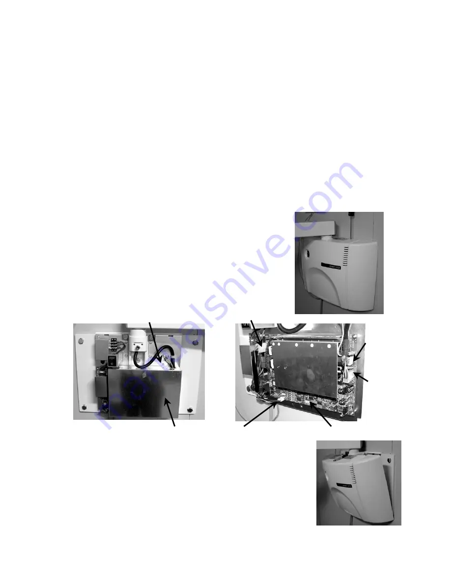
Remove the top two screws and open the front cover. (Fig. 1)
2. Remove the two screws which secure the shield box. Then remove
the shield box. (Fig. 2)
3. Disconnect the four connectors (2P, 3P, 4P and 8P) from the power PC
board. (Fig. 3)
4. Remove the four screws which secure the power PC board. Then
remove the PC board.
Screw for shield box
Fig. 2 Fig. 3
Power PC Board
4P connector
3P connector
8P
connector
2P
connector
Fig. 1
Shield box
5. Place the new power PC board in position and secure it with four screws.
One of the four screws has no flat washer, and it should be placed in the
bottom left corner.
6. Attach the four connectors to the power PC board again, being careful not to
bend the PC board.
7. Attach the shield box with the two screws, being careful not to pinch the
wires.
8. Attach the front cover and secure with the two screws which were removed in
step 2.
Fig. 4
-27-


