A D 2 4 0 2 - 9 6 - O P E R A T I N G M A N U A L
Important Note:
If the “Word Length” switch is set at “24”, the “D-to-D” mode
will alter the status bits but will not alter audio data bits. All other “Word Length”
settings will add dither noise to the audio.
Use the “24” setting whenever you do
not wish to alter the word length of the audio signal
. However, if you wish to
reduce the word length of the audio data, use the “Word Length” switch to select
the desired word length reduction function. See
Table 1
.
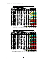
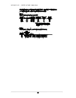
T a b l e 1 - W o r d L e n g t h M o d e S e t t i n g s f o r D - t o D P r o c e s s i n g
Input Word Length Output Word Length Word Length Mode Switch Settings
16
16
24
18
16
16NS3, 16NS2, 16NS1, 16 NN3, 16NN2, 16NN1, or 16TPDF
18
18
24
20
16
16NS3, 16NS2, 16NS1, 16 NN3, 16NN2, 16NN1, or 16TPDF
20
20
24
24
16
16NS3, 16NS2, 16NS1, 16 NN3, 16NN2, 16NN1, or 16TPDF
24
20
20NS2, 20NS1, 20NN1, 20TPDF
24
24
24
“Meter Scale” Switch
The “Meter Scale” switch selects one of
three digital meter functions.
The down position sets
the meter scale to
6-dB steps
. The center position sets the meter scale to
1-dB steps
. The up
position sets the meter scale to
1-dB steps with peak hold
. Moving the switch to the center
position will clear the peak hold. Note that the bottom of the 1-dB scale is expanded and includes
a -20 dBFS LED that can be used to set the input level relative to a 0-dB house reference.
The “6
dB” setting makes it easy to verify that signals are present at the analog inputs. The “1 dB”
and “Hold” settings permit accurate monitoring near full scale.
15


