A D 2 4 0 2 - 9 6 - O P E R A T I N G M A N U A L
most 24-bit A-to-D converters. This is important because our ears act much like a super
resolving FFT analyzer.
Why Does Sample-Clock Jitter Need to be so Low?
It can be easily demonstrated that most people have the ability to detect and identify tones
which are buried 25 dB or more below white noise (A-Weighted). Therefore, it is important
to keep jitter induced side bands nearly 25 dB below the A-Weighted THD+N of the
converter, otherwise the jitter may become audible.
Jitter can only be considered totally inaudible if the worst case jitter induced sidebands are at
least 23 dB below the A-weighted system noise. Above this level jitter may be audible or it
may be masked by the program audio. At Benchmark our goal is to achieve totally inaudible
levels of jitter.
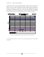
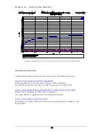
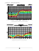
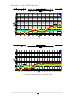
The FFT analysis shown in Figure 4 demonstrates the ability of the AD2402-96 to resolve
tones as low as -140 dBFS. Note that in this test, the AD2402-96’s highest jitter induced side
bands occur at 4 kHz and 6 kHz. These each measure at an extremely low -140 dBFS and
indicate that jitter at 6 kHz (a common problem frequency) is below 5 Pico-seconds. The
AD2402-96 has an idle channel THD+N of better than -117 dBFS (A-Weighted) and jitter
induced side bands are held 23 dB below this level. It is this level of performance, which
makes the AD2402-96 unique.
Jitter Degrades Digital Anti-Alias Filters
The performance of oversampled A/D converters is highly dependent upon very precise
digital filters. These digital filters provide a brick wall that stops unwanted high frequency
signals. In the case of 44.1 kHz conversion, this brick wall filter is constructed such that it
stops all frequencies above 22.05 kHz (one half of the sample rate). Frequencies above
22.05 kHz cannot be represented in a 44.1 kHz digital system. If these frequencies are not
removed, aliasing will occur. When aliasing occurs, high frequency information is translated
or folded back into the audio band.
Oversampled converters use digital filters to prevent aliasing, non-oversampled converters
rely solely upon analog filters in front of the A/D sample and hold circuit. Analog filters
require closely matched resistors and capacitors, parts with low temperature coefficients, and
lots of space on a circuit board. A digital filter can easily outperform the best analog filter.
Digital filter performance is generally limited only by the number of arithmetic operations
that we are willing to perform for each sample of audio that passes through the filter. State
of the art A/D converter ICs have digital filters that can achieve remarkable levels of
performance. For example, at a 44.1 kHz sample rate, the digital anti-alias filter in the
AD2402-96 achieves 117 dB of attenuation at all frequencies between 24.44022 kHz and
2.798145 MHz while the response at 20.30364 kHz is –0.01 dB! However, this performance
can
only
be achieved in the absence of jitter.
When a digital filter is designed, jitter is assumed to be zero. A digital filter consists of a
series of delay elements, multipliers, and summing nodes. The delay elements are assumed
32


