background image

Page 22

Page 23

BOILERMA

TE 

2000

2.2 INSTALLATION

Electrical Connection - Standard Appliance

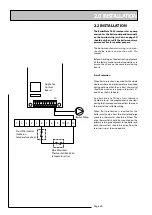
The BoilerMate 2000 is pre-wired to a 12 way 
terminal strip from the A.C.B. and plumbers are 
well able to complete the electrical installation 
provided  they  adhere  strictly  to  the  IEE 
Requirements  for  Electrical  Installations  BS 
7671.  A schematic arrangement of the wiring 
is shown on page 24.

All the terminals are suitably labelled.

Note: 

Do  not  attempt  the  electrical  work 

unless  you are  competent  to  carry  it  out  to 
the above standards.

Before  commencing  check  that  the  power 
source is in accordance with section 1.2 Site 
Requirements and ensure that it is isolated.  

Run the external wiring through the service 
slot provided in the base of the appliance.

It is recommended that the 3 core input cable 
from the isolator to the appliance is not less 
than 1.5mm

PVC grade to BS 6500.

Clamp the cables in the grips provided below 
the  terminal  strip  and  ensure  all  cables  are 
routed to avoid hot surfaces.

Note

: The appliance is provided with a 4.0mm 

earth  cable  from  an  earthing  strap  on  the 
primary  return  (to  boiler)  pipe  to  the  earth 
stud on the wiring panel.

2.0  INSTALLATION

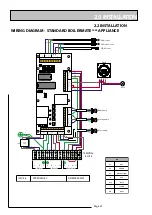
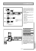
Make the connections as shown opposite on 
the terminal strip provided.

The  appliance  is  provided  with  a  link 
between terminals 9 and 11 on the terminal 
strip.   This  must  be  removed  if  a  room 
thermostat is fitted see opposite.

L

E

N

L

E

N

SL

L

E

N

SL

ROOMSTAT

BOILER

MAINS 

1

2

3

4

5

6

7

8

9

10

11

12

INCOMING

POWER 

SUPPLIES

230V 50 Hz

3 amp

OUTGOING

SUPPLY

TO BOILER

OUTGOING 

SUPPLY TO

ROOMSTAT 

(IF FITTED)

LINK

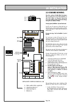
No Clock Models

•  If a remote clock is not being provided links 
  will be required between 21/22 and 22/23.
•    If  a  single  remote  clock  is  being  provided 
  a single link will be required between 21/22 
  to allow the appliance to provide hot water 
  24hrs/day.
•  If  a  two  channel  clock  is  being  provided 
  no  links  will  be  required.  (A  two  channel 
  clock is normally only required to eliminate 
  noise caused by the boiler firing during the 
  night).
•  Wire  the  connections  from  the  clock  as 
  shown opposite.

Wiring guide from Clock to ACB

Neutral - Terminal 20

Permanent Live (to clock) - Terminal 21

Hot Water Channel Switched Live (from clock) - Terminal 22 
(only required with 2 channel clock)

Heating Channel Switched Live (from clock) - Terminal 23

Summary of Contents for Gledhill BoilerMate 2000 125

Page 1: ...MAINS PRESSURE HOT WATER SUPPLY SYSTEM INCORPORATING A THERMAL STORE ALL MODELS COMPLY WITH THE WATER HEATER MANUFACTURERS SPECIFICATION FOR INTEGRATED THERMAL STORES BOILERMATE 2000 BOILERMATE 2000 G...

Page 2: ...ity System audited by BSI Patents Pending TheGledhillGroup sfirstpriorityistogivea high quality service to our customers Quality is built into every Gledhill product and we hope you get satisfactory s...

Page 3: ...BoilerMate 2000 is not covered by section G3 of the current Building Regulations and is therefore not notifiable to Building Control The information in this manual is provided to assist generally in...

Page 4: ...The outlet temperature of the domestic hot water is maintained by a printed circuit board which controls the speed of the pump circulating the primary water from the store through the plate heat exch...

Page 5: ...e d o M 5 2 1 M B 5 4 1 M B 5 8 1 M B 0 1 2 M B 5 2 2 M B y t p m e t h g i e W g k 8 5 g k 1 6 g k 5 6 g k 6 7 g k 8 8 l l u f t h g i e W g k 3 7 1 g k 6 8 1 g k 5 1 2 g k 6 4 2 g k 8 7 2 p m u P W...

Page 6: ...ion cistern complete with ballvalve overflow fitting and cold feed open vent pipework assembly is supplied separately Optional Equipment A soft water model is available for areas where the hardness le...

Page 7: ...O I S N E M I D E C N A I L P P A l e d o M t h g i e H h t d i W h t p e D A B C 5 2 1 M B m m 0 4 1 1 m m 5 9 5 m m 5 9 5 5 4 1 M B m m 0 4 1 1 m m 5 9 5 m m 5 9 5 5 8 1 M B m m 0 5 3 1 m m 5 9 5 m...

Page 8: ...Page 8 1 0 DESIGN 1 2 TECHNICAL DATA...

Page 9: ...BOILERMATE 2000 1 2 TECHNICAL DATA AWAITING HOT WATER PERFORMANCE GRAPHS FOR EACH MODEL SIZE PERFORMANCE GRAPHS OF GRUNDFOS PUMPS 1 0 DESIGN GRUNDFOS 15 50 litres sec 6 litres sec GRUNDFOS 15 60 TO BE...

Page 10: ...optional extra are being used or if all taps are provided with flow regulators the flow regulator on the cold inlet should be removed No check valve or similar device should be fitted on the cold wat...

Page 11: ...ed fully in accordance with their recommendations This is particularly important in relation to use of push fit connections when using the optional flexible hose kits see 2 2 Installation Pipework con...

Page 12: ...vity circulation does not occur when the heating pump is not running To be certain of preventing this it is recommended that a check valve or valves are fitted on the vertical flow pipes Thewaterlevel...

Page 13: ...ework systems can be used in place of copper internally as long as the chosen system is recommended for use on domestic heating systems by the manufacturer and is installed fully in accordance with th...

Page 14: ...erMate 2000 and the boiler during dormant periods An automatic air vent will be required on the flow adjacent to the boiler and depending upon the pipe layout a manual air vent may also be required on...

Page 15: ...lockshield valves on the radiators If this is not done the performance of the BoilerMate will be adversely affected If heating of a single bathroom radiator or towel rail is required in summer then it...

Page 16: ...e system that has been installed If the primary pipework dips or the boiler is located above the BoilerMate a single F E cistern with a cold feed and open vent piped to the cistern should be used This...

Page 17: ...heating modes In the former only hot water pump and electric heating element are energized In the latter the heating system pump is also energized This means that the heating will be on permanently u...

Page 18: ...mperatures will normally be higher than in a conventional system and the design of the cupboard and door will need to take this into account No ventilationisnormallyrequiredtothecupboard A suitable lo...

Page 19: ...ecommended method is shown opposite Before installation the site requirements should be checked and confirmed as acceptable The plastic cover and protective wrapping should be removed from the applian...

Page 20: ...on fittings Connection E is blanked 15mm copper pipe Connection J is RC1 2 1 2 in BSPT internal A Safety open vent B Cold feed expansion C Primary flow from boiler D Primary return to boiler E Towel r...

Page 21: ...F E cistern and pipework site run by the installer to connect this to the appliance Obviously any pipework in the roof space and the feed and expansion cistern will need to be adequately insulated to...

Page 22: ...age 22 WIRING DIAGRAM STANDARD BOILERMATE 2000 APPLIANCE 2 0 INSTALLATION 2 2 INSTALLATION Y E K L B E U L B R B N W O R B Y G W O L L E Y N E E R G R D E R K L B K C A L B Y W O L L E Y H W E T I H W...

Page 23: ...from an earthing strap on the primary return to boiler pipe to the earth stud on the wiring panel 2 0 INSTALLATION Make the connections as shown opposite on the terminal strip provided The appliance...

Page 24: ...Frost Protection When frost protection is required for the whole house or where a base temperature is required during cold weather then a frost thermostat should be wired across plug in terminals 21 a...

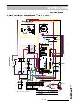
Page 25: ...Page 25 BOILERMATE 2000 2 0 INSTALLATION 2 2 INSTALLATION WIRING DIAGRAM BOILERMATE2000 WITH SWITCH...

Page 26: ...e service slot provided in the base of appliance The recommendations contained under Electrical Connection Standard Appliance should be followed when connecting a remote clock room thermostat boiler e...

Page 27: ...n Check the water level in the feed and expansion cistern and adjust the ballvalve if necessary Check the whole of the primary heating and domestic hot and cold distribution systems for leaks It is es...

Page 28: ...MAXIMUM 2 Switch off heating on the clock programmer and room thermostat 3 Switch off hot water on the programmer if 2 channel clock is fitted 4 Check the jumper settings are correct These must all be...

Page 29: ...heating pump will run continuously This product is covered by the Benchmark scheme and a separate commissioning service log book is included with this product This must be completed during commissioni...

Page 30: ...T use a BoilerMate on a sealed primary i e closed system 13 DON T use pipe smaller than 28mm between the boiler and the BoilerMate when the boiler rating exceeds 20kW about 68 000 Btu h 14 DON T use d...

Page 31: ...ts specialist heating spares suppliers Help and advice is also available from the Technical Helpline on 01253 474401 However allcomponentsarereadilyaccessible and can be changed quickly and easily by...

Page 32: ...a l P p e w S 7 1 0 T G 4 6 6 5 0 E 0 1 B C A d r a o b l o r t n o c e c n a i l p p A k o l E 5 5 2 B X 8 5 1 9 3 E 1 1 r o s n e s e r o t S k o l E 9 4 1 T G 2 2 0 6 2 E 2 1 r o s n e s n r u t e...

Page 33: ...Page 33 BOILERMATE 2000 3 0 SERVICING...

Page 34: ...at the space heating and hot water load is not greater than the boiler output and that the BoilerMate 2000 model is suitable for the type of dwelling If all the above checks are satisfactory then it i...

Page 35: ...tric backup this should be switched on and operated in accordance with the instructions on the label fitted to the appliance until the installer manufacturer can attend When requesting a visit from th...

Page 36: ...s as in Option 4 for Taps Mixers APPENDIX A WATER SAVINGS OPTIONS FOR SHOWERS 4 FIXING OPTIONS FOR TAPS MIXERS 1 MK Range Combined Regulators Aerator for screwing onto Taps Mixers with internal or ext...

Page 37: ...d close to the appliance if required 0 5 0 P I M e d o C k c o t S 1 e p y t d l o f i n a M m o o r k a o l c e n o m o o r r e w o h s e t i u s n e e n o m o o r h t a b e n o r o t a l u g e r w o...

Page 38: ...ework in table 2 r e p p o c m m 5 1 n i h t g n e l e p i p t n e l a v i u q e m u m i x a M 1 e l b a T e r u s s e r p t e l n I r a b m e p i p f o h t n e l t n e l a v i u q e m u m i x a M m l...

Page 39: ...al connection of fittings to the manifold will need to suit the arrangements shown on page 35 Note 1 If it is proposed to fit chemical water treatment such as a water softener this should be fitted in...

Page 40: ...he contractors installers reasonable costs in removing and replacing any defective Open Vented Copper Cylinder or Tank with defective integral pipework as follows Gledhill Water Storage Ltd AMD AUGUST...

Page 41: ...ses owned or occupied by the Purchaser or in the possession of the Purchaser for the purposes of repossessing and recovering any such goods the property in which has remained in us under paragraph 2 a...

Page 42: ......

Page 43: ......

Page 44: ......

Reviews: