background image

6 720 611 443 GB (05.04)

6

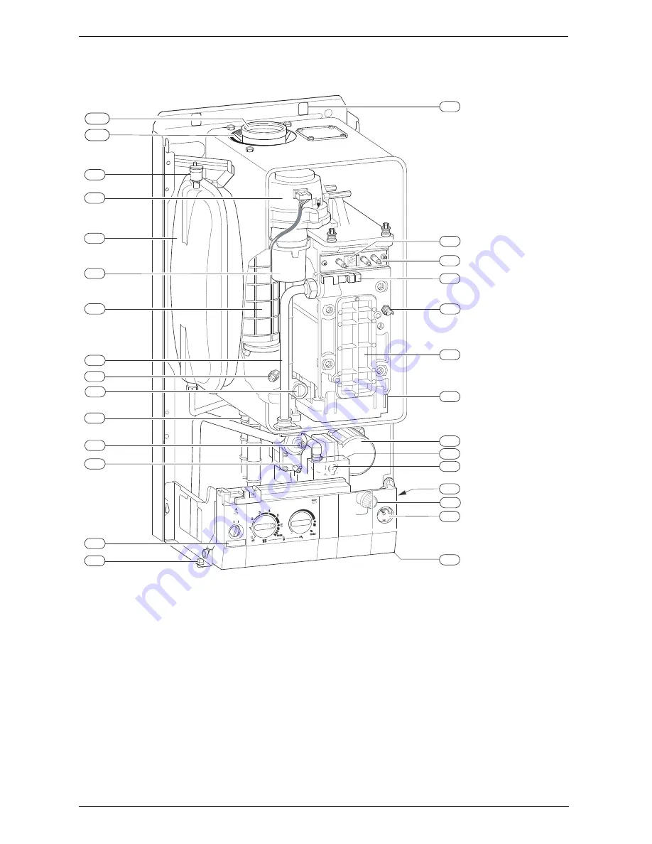
Details of the appliance

1.6

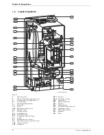
Layout of appliance

Fig. 2

4

Heatronic control

6

Heat exchanger safety temperature limiter

7

Testing point for gas supply pressure

8.1

Pressure gauge

9

Flue gas temperature limiter

15

Relief valve

18

Pump

18.1

Pump speed selector switch

20

Expansion vessel

27

Automatic air vent

29

Air gas Mixer unit

32.1

Electrode assembly

36

Temperature sensor in CH flow

43

CH flow

63

Adjustable gas flow restrictor

64

Adjusting screw for min. gas flow volume

102

Inspection window

120

Fixing points 

221.1

Flue duct

221.2

Combustion air intake

226

Fan assembly 

295

Appliance type sticker

271

Flue duct

358

Condensate trap

415

Cover plate for cleaning access

416

Condensate collector

417

Clip for fixing outer case

418

Data plate

423

Siphon

.TD

18.1

423

27

8.1

29

102

226

271

416

20

43

9

63

358

64

7

417

15

4

18

415

6

36

32.1

120

418

295

6 720 611 443-01.1O

221.2

221.1

Summary of Contents for ZB 7-28 R 28 HE

Page 1: ...GB IE Installation and Servicing Instructions R 28 HE system Wall mounted condensing boiler for central heating 6 720 611 441 00 1O ZB 7 28 R 28 HE System GC Number 41 311 62 6 720 611 443 GB 05 04 OSW ...

Page 2: ...ion vessel 27 6 1 2 Setting the central heating flow temperature 27 6 1 3 Changing the heating pump characteristic 27 6 2 Settings on the Bosch Heatronic 28 6 2 1 Operating the Bosch Heatronic 28 6 2 2 Selecting the pump control mode for central heating mode Service Function 2 2 28 6 2 3 Setting the anti cycle time Service Function 2 4 28 6 2 4 Setting the maximum CH flow temperature Service Funct...

Page 3: ... appliance works and how to operate it B Advise the user that he she must not make any modi fications to the appliance or carry out any repairs on it B These instructions are to be left with the user or at the Gas meter B Important These instructions apply in the UK only EIRE ONLY The CE mark to indicates manufacture to EU safety requirements This appliance must be installed only by a competent pe...

Page 4: ...siting not dependent on room size Natural gas models are low emission appliances Multi function display Bosch Heatronic control system Automatic ignition Modulating control Full safety systems incorporating Bosch Heatronic with flame ionisation monitoring solenoid valves and temperature sensors Concentric flue air duct with testing point for CO2 CO Regulated speed fan Pre mix burner Temperature co...

Page 5: ...rammer Night Set Back Module and TR2 Optimising Room Thermostat will be required 1 5 Casing dimensions Fig 1 13 Manifold assembly 101 Outer case 103 Facia cover X Standard Concentric Horizontal Flue System min 160 mm Alternative Concentric Flue System min 220 mm Y Standard Concentric Horizontal Flue System 40mm Alternative Concentric Flue System 70mm Z Standard Concentric Horizontal Flue System 10...

Page 6: ...t 32 1 Electrode assembly 36 Temperature sensor in CH flow 43 CH flow 63 Adjustable gas flow restrictor 64 Adjusting screw for min gas flow volume 102 Inspection window 120 Fixing points 221 1 Flue duct 221 2 Combustion air intake 226 Fan assembly 295 Appliance type sticker 271 Flue duct 358 Condensate trap 415 Cover plate for cleaning access 416 Condensate collector 417 Clip for fixing outer case...

Page 7: ...sing electrode 33 Igniter electrode 35 Heat exchanger with cooled combustion chamber 36 Temperature sensor in CH flow 43 CH flow 45 Gas inlet 47 CH return 52 Solenoid valve 1 52 1 Solenoid valve 2 55 Filter 56 Gas valve CE 427 57 Main valve disc 61 Reset button 63 Adjustable gas flow restrictor 64 Adjusting screw for min gas inlet flow volume 69 Control valve 71 Storage water heater outflow only w...

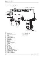
Page 8: ...Transformer 161 Link 226 Fan 300 Code plug 302 Earth connection 310 Temperature control for hot water 312 Fuse slow T 1 6 A 313 Fuse slow T 0 5 A 314 Connector for Night Set Back Module TA212E 318 Connector for integral programmer 328 Terminal block for AC 230 V Mains supply 328 1 Link 363 Indicator lamp for burner 364 Indicator lamp for power supply 365 Chimney sweep button 366 Service button 367...

Page 9: ...t 88 MJ m3 mbar 37 Expansion vessel Charge pressure bar 0 75 0 75 Total capacity l 10 10 Flue Flue gas temp 80 60 C rated min load C 67 55 67 55 Flue gas temp 40 30 C rated min load C 43 32 43 32 Residual delivery pressure inc pressure drop in air intake duct Pa 80 80 CO2 level at max rated heat output CO2 level at min rated heat output 9 2 8 8 10 8 10 5 NOx class 5 5 SEDBUK figure Band A A Conden...

Page 10: ...ating for Domestic Premises BS 5546 Installation of gas hot water supplies for domestic purposes BS 5440 1 Flues and ventilation for gas appliances of rated input not exceeding 70 kW net Flues BS 5440 2 Flues and ventilation for gas appliances of rated input not exceeding 70 kW net Air Supply BS 6891 Installation of low pressure gas pipework installations up to 28 mm R1 BS 7074 1 Code of practice ...

Page 11: ... low level and arranged as shown in fig 8 The pressure relief valve is set to operate at 3 bar There must be no connection to the mains without the approval of the local water company All connections in the system must be capable of withstanding a pressure of up to 3 bar and the radiator valves conform to the requirements of BS 2767 10 Fit Thermostatic Radiator Valves to radiators in the sleeping ...

Page 12: ...er Return Hot Water Flow BS Stop Valve Fixed Cylinder Type Mains Cold Water Radiator Valve Flow RV Lockshield Valve Return LV Note A drain cock should be fitted at the lowest point of the heating circuit and beneath the appliance 6 720 610 601 04 1O 6 720 610 601 05 1O RV LV LV RV RV RV LV LV INDIRECT CYLINDER APPLIANCE Refer to Appliance Water Flow Diagram Heating Return Heating Flow Safety Disch...

Page 13: ...g and the flue is less than 85 C This means that no special safety precautions are required with regard to flammable building materials and fitted furniture The specified clearances must be maintained Cupboard Compartment The appliance can be installed in a cupboard compart ment need for airing clothes providing that the require ments of BS 6798 and BS 5440 2 are followed The low casing losses fro...

Page 14: ...with the screws provided B Mark the position of the flue duct hole if a rear flue is to be used Refer to fig 1 and 18 Fig 10 B Screw the pre plumbing manifold with two screws to the wall mounting frame Fig 11 3 5 Pre piping the system Fig 12 Manifold 43 CH flow 47 CH return 112 Gas cock 171 Optional cylinder flow used only with motorised valve 172 Optional cylinder return used only with motorised ...

Page 15: ...uns and with a downward slope of at least 2 5 3 6 Fitting the appliance Removing the outer case B Remove retaining screws 1 B Slide the outer case upwards and then forwards to remove 2 B Remove the plastic caps from the boiler connections Fig 15 Boiler Boiler Sink Ø 22 min Ø 22 min Ø 22 min Ø 22 min Siphon Siphon Invert No length restriction No length restriction No length restriction Internal soi...

Page 16: ...essure on the gas supply pipe 3 8 Flue Systems The only flue systems that may be used are those sup plied with the boiler The flue system must be installed in accordance with the requirements of BS 5440 1 Standard 100 mm flue system The standard concentric flue system provides for a hor izontal length of up to 4 m Full instructions for fitting this flue are in Subsection 3 8 2 Installation of the ...

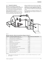
Page 17: ... C D E J N Q F P Q B I L N N M M Q I 6 720 611 400 25 1O Dimension Terminal position kW input expressed in net Balanced flues room sealed Fanned draught A1 Directly below an opening air brick opening windows etc 300 mm B1 Above an opening air brick opening window etc 300 mm C1 Horizontally to an opening air brick opening window etc 300 mm D Below gutters soil pipes or drain pipes 75 mm E Below eav...

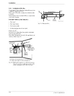
Page 18: ...vant flue kit Check that the position chosen for the appliance is sat isfactory Refer to fig 18 Fig 18 Marking the position of a side flue opening Note ensure ther is adequate access to the air flue sampling points in the flue turret Fig 19 Standard Flue Centre line of flue air duct Centre line of flue opening and appliance Drilling point for flue duct opening H 40mm for the Standard 100mm Horizon...

Page 19: ...e components Maximum 1700mm Clamp Flue Turret Terminal Assembly Outer Wall 6 720 611 400 19 1O Extension Duct Clamp Flue Turret Terminal Assembly Outer Wall 6 720 611 400 20 1O Extension Duct Extension Duct Clamp Clamp Clamp Flue Turret Extension Flue Duct Flue Terminal Wall Sealing Gasket 6 720 611 400 21 1O ...

Page 20: ...e assembly will be made easier if a solvent free grease is lightly applied i e Silicone lubricant to the male end of the ducts NOTE An inner wall sealing plate is provided which should be fitted to the ducts before assem bly Push the assembly through the wall and fix the turret to the appliance using the screws prefitted to the boiler flue outlet Refer to fig 26 Fig 26 Flue turret Ensure that the ...

Page 21: ...blanking plate 4 1 Connecting the appliance To gain access to the mains connection remove the drop down facia cover The drop down cover is removed by lowering it to the horizontal position and pushing firmly upwards at the rear of the supports to release the cover Lift cover from the appliance After installation or in the event of an electrical fault the electrical system shall be checked for shor...

Page 22: ...his can be obtained from an electronics wholesalers such as Farnell Tel 0870 1200 202 The Farnell part number for this capacitor is 869 491 See section 4 1 to gain access to the boiler mains wiring centre Remove the connecting link from LS and LR terminals and connect the system to the boiler Two typical examples of this are shown in Fig 31 and Fig 32 Any other components including frost thermosta...

Page 23: ...pplied with each part Externally wired frost protection is not required as this is provided by the boiler s internal frost thermo stat and the TR2 room thermostat L N N L LR S S TIME CONTROLLER GREY ORANGE G YELLOW WHITE BLUE N L SW C 2 1 ROOM STAT CYLINDER STAT N HW OFF HW ON L 1 2 3 4 5 6 7 8 9 10 MID POSITION ZONE VALVE 6 720 611 443 05 1O Description Part Number 24v Diverter valve including ta...

Page 24: ...s boiler and its associated cen tral heating system should be flushed in accordance with the guidelines given in BS 7593 1992 Treatment of water in domestic hot water systems Full instructions are supplied with proprietary cleansers sold for this pur pose If an inhibitor is to be used after flushing it should be used in accordance with the inhibitor manufacturers instructions To drain the applianc...

Page 25: ...ng in the central heating mode Fig 34 The trap filling programme ensures that the condensa tion trap is filled after the appliance has been installed or after the appliance has been out of use for a long period or the mains supply has been interrupted For that reason the appliance remains at minimum heating output for 15 minutes Switching off the appliance B Set the master switch to 0 The green in...

Page 26: ...earborn Tel 0151 4209563 and Fernox Tel 01799 550811 5 7 Pump anti seize function Every time the pump is switched off a timer is started If after 24 hours the pump has not run again it is switched on for a period of 5 minutes 5 8 Fault Condition In the unlikely event of a fault occurring while the appli ance is in operation The display then shows a fault code and the button may also flash If the b...

Page 27: ...iver Fig 37 B Rotate yellow button through 180 and replace dot facing inwards The CH flow temperature is no longer limited 6 1 3 Changing the heating pump characteristic The speed of the central heating pump can be altered on the pump terminal box Fig 38 1 Pump characteristic for switch position 1 2 Pump characteristic for switch position 2 3 Pump characteristic for switch position 3 H Residual de...

Page 28: ...ode for cen tral heating mode Service Function 2 2 The choice of settings is as follows Control Mode 1 For heating equipment without a control unit The pump is controlled by the central heating flow temperature control Control Mode 2 factory setting For heating systems with room thermostat The central heating flow temperature control controls only the gas the pump is not affected The room ther mos...

Page 29: ...ating and cylinder charging output to obtain the relevant code for the desired heating output in kW see page 43 B Turn the temperature control until the display shows the desired code number The display and the and buttons will flash B Measure the gas flow rate and compare with the fig ures specified for the code number displayed If fig ures do not match adjust the code number B Press and hold the...

Page 30: ...ster switch O B Remove the outer case see page 15 refer to fig 15 B Switch on the appliance at the master switch I B Set room thermostat to maximum temperature B Open thermostatic radiator valves B Unscrew sealing plug from flue gas testing point 234 Refer to fig 43 B Insert testing probe about 135 mm into the flue gas testing point and seal testing point Fig 43 B Press and hold button until the d...

Page 31: ...B Recheck the levels at min and max rated heat output and re adjust if necessary B Turn the temperature control anti clockwise as far as the stop so that the display shows 0 Normal operating mode The display and the button will flash B Press and hold the button until the display shows B Reset the temperature controls and to their original positions The display will revert to the CH flow temperatur...

Page 32: ...active The button will light up and the display shows the CH flow temperature B Remove sealing plug from flue gas testing point 234 fig 50 B Insert testing probe about 135 mm into the testing point and seal testing point B CO and CO2 levels B Refit sealing plug B Press and hold button until the display shows The button will stop flashing and the display shows the CH flow temperature i By testing t...

Page 33: ...pressure relief valve B To drain the appliance shut the system valves and open the pressure relief valve B Upon completion of any electrical work check for earth continuity correct polarisation and resistance to earth B Always disconnect the appliance from the electrical power supply fuse circuit breaker before carrying out any work on the electrical systems or components B Always turn off the gas...

Page 34: ...age 30 mbar 5 Test combustion air flue gas see page 32 6 Check CO2 setting for min max gas air ratio see page 30 min max 7 Check gas and water systems for leaks see page 16 8 Check heat exchanger see page 35 mbar 9 Check burner see page 36 10 Clean condensation trap see page 36 11 Check charge pressure of expansion vessel matches static head of heating system mbar 12 Check central heating system p...

Page 35: ... 32 1 page 6 must be cleaned or replaced Primary Heat exchanger There is a special accessory kit no 840 for cleaning the heat exchanger order no 7 719 001 996 B Check control pressure on the air gas mixer unit at max rated heat output using an electronic manome ter Fig 51 B Remove cleaning access cover 415 page 6 and the metal plate below it if present Refer to fig 2 B Unscrew condensation trap an...

Page 36: ...der inspect seal for damage and replace if necessary B Adjust gas air ratio Refer to section 7 2 Condensation trap In order to prevent spillage of condensate the conden sation trap should be completely removed see page 35 fig 52 B Unscrew condensation trap and check connection to heat exchanger is clear B Remove condensation trap cover and clean B Fill condensation trap with approx 1 4 l of water ...

Page 37: ...stem Heating system pressure B The pointer on the pressure gauge should be 1 bar B If the pointer is below 1 bar when the system is cold water should be added until the pointer is 1 bar again B Max pressure of 2 5 bar when the heating system water is at maximum temperature must not be exceeded If this pressure is exceeded then an extra expansion vessel must be fitted in the system return as close ...

Page 38: ...to fig 27 28 B Remove screw holding power connector earth lead and remove earth lead B Remove two top fixing screws from the control box Refer to fig 63 Fig 60 B Lower the control box B Unscrew earth lead B Unscrew four fixing screws from cover plate Refer to fig 64 B Prise off cover plate B Pull off transformer B Remove pcb holder B Remove the pcb control board Fig 61 Fuses B Remove the connectio...

Page 39: ...x fixing screws 1 Refer to fig 63 B Lower switchbox 2 B Unscrew and remove the siphon by releasing the jubilee clip Refer to fig 59 B Unscrew the pump union nuts 3 Refer to fig 63 B Carefully remove the pump and disconnect the leads Alternatively B After removing the siphon release the four Allen screws and remove and replace the pump head Fig 63 8 3 4 Optional 3 way diverter valve B Switch off th...

Page 40: ...perature Limiter Item 9 fig 2 63 B Pull off the connectors B Unscrew the sensor 8 3 7 Gas Valve B Check that the gas cock is turned off B Lower the control panel Refer to fig 63 B Pull off the solenoid connections at the rear of the valve B Undo the union within the inner casing securing the valve to the gas air tube Refer to fig 62 B Remove the white plastic cap from the gas valve B Release the g...

Page 41: ...er B Refer to section 8 2 8 3 13 Primary Heat Exchanger B Drain the appliance B Check that the gas supply is turned off B Check that the appliance is electrically isolated B Remove the fan assembly complete with the gas air tube and mixer assembly Refer to section 8 3 2 B Remove the burner Refer to section 8 2 B Disconnect the sensors Refer to section 8 3 6 B Undo the central heating flow union B ...

Page 42: ...or and connecting lead E9 Safety temp limiter in CH flow has tripped Check system pressure check safety temp limiters check pump operation check fuse on pcb bleed appliance EA Flame not detected Is gas cock turned on Check gas supply pressure power supply igniter electrode and lead ionisation sensing electrode and lead flue duct and CO2 level F0 Internal error Check electrical connector contacts p...

Page 43: ... 401 999 0 11 Pump 1 8 717 204 384 0 12 Pressure gauge 1 8 717 208 079 0 13 Burner skin seal 1 8 711 004 168 0 14 Transformer facia 1 8 747 201 358 0 15 Heat exchanger washer 1 8 710 103 153 0 16 Washer set Condensation Trap 1 8 710 103 154 0 17 Fuse set 1 8 744 503 010 0 18 Primary heat exchanger 1 8 715 406 615 0 Table 19 Natural gas G20 Display code Heat output kW Heat input kW Gas vol flow rat...

Page 44: ...ve set value Pump ON Fan to start speed Gas valve opens Burner stabilises at start speed for 5 10 secs Fan speed reduces over 15 secs Fan min speed for 90 secs Boiler unused for long period Minimum heat input for 15min Boiler operates to match system load and CH control setting Ignition sequence Ignition spark for 5 seconds Burner lights Red light ON Repeats 5 times N G or 3 times L P G before loc...

Page 45: ...6 720 611 443 GB 05 04 Appendix 45 ...

Page 46: ...6 720 611 443 GB 05 04 46 Appendix ...

Page 47: ...6 720 611 443 GB 05 04 Appendix 47 ...

Page 48: ...Appendix Appendix Worcester Bosch Group Cotswold W Tel 01905 754624 Fax 01905 754619 ay Warndon Worcester WR4 9SW Worcester Bosch Group is a trading name of BBT Thermotechnology UK Ltd ...

Reviews: