13
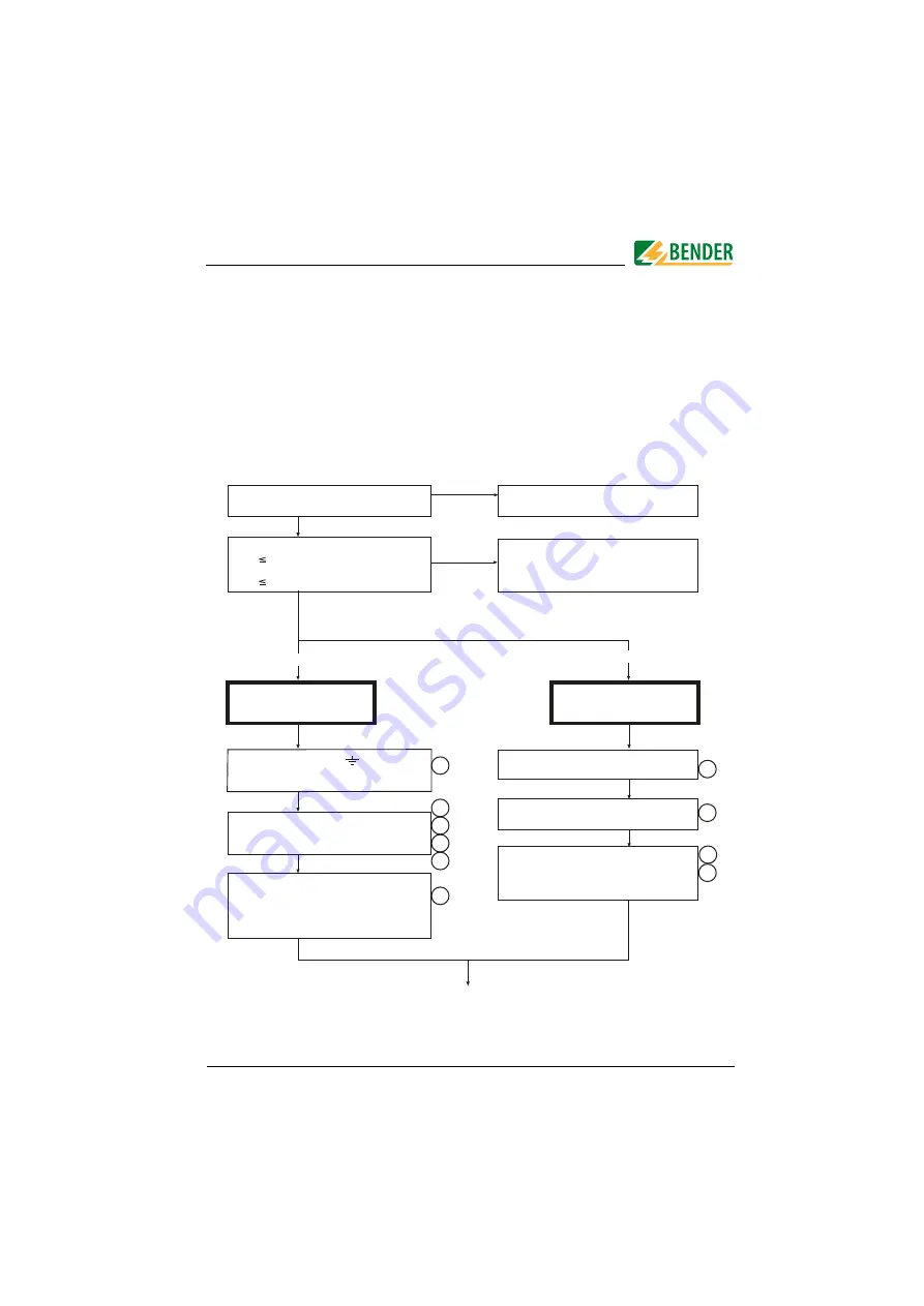
3. Commissioning flow chart
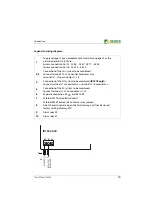
The encircled figures in the flow chart correspond to the figures in the legend
to the wiring diagram (see page 19).
Commissioning of A-Isometer (1)
Is the system to be monitored an
unearthed system (IT system)?
The IR157x is not suitable for this
application( contact BENDER).
Device connection
Optional device
connection
no
no
yes
The terminals L1 and L2 must be
connected to the system to be moni-
tored Un according to the wiring diagram .
Connect the supply voltage Us
to the terminals A0 and A1 (AC/DC 230 V)
or to the terminals A0 and A2 (AC 400 V).
Consider the details indicated on the
nameplate.
External TEST button (NO contact) to the
terminals T1 and T2
External RESET button (NC contact) to the
terminals R1 and R2
The output contacts of the alarm relays
Alarm 1 (11-12-14)
Alarm 2 (21-22-24)
9
7
8
10
Deenergize the installation
before connecting the device!
Recommended wire cross section of
connecting cable
single wire 0.2 ... 4 mm2
flexible 0.2 ... 2.5 mm2
Is the nominal voltage
Un AC 480 V (IR1570/1575) ?
oder
Un DC 480 V (IR1575) ?
yes
The two PE connections and KE must
be connected separately to the
equipotential bonding.
6
2
3
4
5
1
The IR157x is not suitable for this
application( contact BENDER).
Summary of Contents for A-ISOMETER IR1570 Series
Page 16: ...Commissioning flow chart 16 TGH1370en 12 2019...
Page 20: ...Connection 20 TGH1370en 12 2019...
Page 32: ...Operating and setting 32 TGH1370en 12 2019...
Page 43: ......


