TGH1402en/11.2020 19
MF loop monitor
6
Appendix
6.1
Frequency selective current monitor SRCM420
6.1.1 Description of function
Once the supply voltage
U
s
has been applied, the start-up delay “t” starts. During this time, if the
values drop below the response values, this has no influence on the switch state of the alarm re-
lays. The contactor (BS) is therefore not activated during the start-up delay. The current is measu-
red via an external measuring current transformer. The latest measuring value is shown on the LC
display. If the measuring value drops below one or both response values, the set response delays
t
on1/2
start.
Once
t
on1/2
has elapsed, the selected alarm relay trips and the alarm LEDs light up. If the release va-
lue is exceeded before ton elapses, no alarm is output: the LEDs AL1 and AL2 do not light up and
the alarm relay does not trip. The set release time
t
off
starts if the measuring value exceeds the re-
lease value (response value plus hysteresis) again after the alarm relay trips. Once “toff” has elap-
sed, the alarm relay switches back to its initial position. The device function can be tested using
the test button T. The device is parameterised via the LC display and the control buttons on the
front and can be protected by a password.
Connection monitoring
The connections to the measuring current transformer are constantly monitored. If there is an er-
ror, the alarm relays K1/K2 trip without delay and the LEDs AL1/AL2/ON flash (Error Code E01).
Once the error has been eliminated, the alarm relays automatically return to their original positi-
on.
Quick interrogation of the undercurrent response values
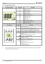
If the display is in standard mode, the latest response values
I
1
and
I
2
can be interrogated by pres-
sing the Up or Down button (< 1.5 s). It is not necessary to switch over to menu mode.
The Enter button must be pressed to leave the quick interrogation.
Automatic self test
Once the system being monitored has been switched on, the device carries out a self test every
24 hours thereafter. During the self test, the internal functional errors are determined and shown
on the display as error codes. The alarm relays are not tested during this time.
Manual self test
Pressing the Test button for > 1.5 s causes the device to carry out a self test where the internal
functional errors are determined and shown on the display as error codes. The alarm relays are
not tested during this time.
While the Test button T is pressed, all the display elements for this device appear on the display.
The test takes place afterwards.
Functional error
If there is an internal functional error, all 3 LEDs flash. The display shows an error code (E01…E32).
E.g. E01 means: connection monitoring faulty.
Summary of Contents for AF460
Page 4: ...4 TGH1402en 11 2020...

