6
ATICS-DIO_D00080_03_Q_DEEN / 11.2020
ATICS-...-DIO
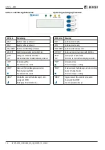
Maße
ATICS-2-DIO
A: Seitenansicht für ATICS-...-DIO
*
Zusätzlicher Platzbedarf für Hilfskontakt bei Einsatz des
Bypass-Schalters
**
Ausschnitt der Verteilerabdeckung anpassen
***
Maße für Schraubmontage auf Platte
****
Zusätzlicher Platzbedarf für Anschlussstecker Mess-
stromwandler
*****
Ausführung 80 A/125 A. Ausführung 160 A ohne
Steckverbinder
Montage
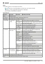
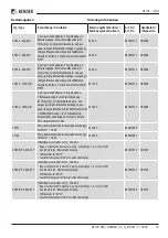
Benötigtes Werkzeug
Zum Anschließen des Leistungsteils und der
Steuerleitungen folgendes Werkzeug verwenden:
• Torx® Schraubendreher T20 oder
6,5 x 1,2 mm
• Schraubendreher 2,5 x 0,4 mm
• Sechskantschlüssel 4 mm
I
Z
erstörungsgefahr
durch Eingipsen.
Flüssiger Gips kann in das Gerät laufen und
es blockieren. Gerät nicht eingipsen.
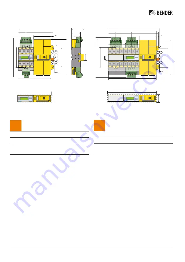
Dimensions
ATICS-4-DIO
A: Side view for ATICS-...-DIO
*
Additional space required for the auxiliary contact
when using a bypass switch
**
Adapt the cutout to the terminal cover
***
Dimensions for screw mounting on mounting plate
****
Additional space required for the connector plug of the
measuring current transformer
*****
Version 80 A / 125 A. Version 160 A without connectors
Mounting
Tools required
Use the following tool to connect the power section
and the control cables:
• Torx® screwdriver T20 or 6.5 x 1.2 mm
• Screwdriver 2.5 x 0.4 mm
• Allen key 4 mm
I
r
isk
of destruction by plastering Liquid
plaster may run into the device and the
device may jam.
Do not seal the device with
plaster.
46
73,5
52
45
222 **
47
234
176 ***
115,3
14,7
52
220
26
3
132 **
*
13
2
24
5
M5
18
*
A
47
326 **
340
115,3
176 ***
104 ***
52
14,7
324
263 ****
*
132 **
*
23 ***
*
15
13
2
24
5
M5
18
*


