background image

Basic programs

70

VMD460-NA_D00001_05_M_XXEN/01.2020

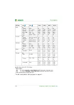
6.10  G99/1-4:2019 

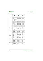
G99 menu: 

once  

twice 

Profile 1 

3)

Profile 2 

3)

Profile 3 

3)

Exit
1. General

Exit
1. Standard

4105_2, 4105_1, 4110, 
BDEW,  0126, CEI021, 
C10/11, G98, G83/2
G99, G59/2

G99

G99

G99

2. Profile

1…3

1

2

3

3. Coupling

1 AC; 3N AC; 3 AC

3N AC

3N AC

3N AC

4. U

(L-N)  

/  U

(L-L)

50…260 V; 87…450 V

U(L-N) 230 V

U(L-N) 230 V

U(L-N) 230 V

5. t 

SHORT INT.

off; 40 ms…60 min

off

off

off

6. t 

(ON) SHORT INT.

40 ms…60 min

––

––

––

7. t 

(ON) NORMAL

40 ms…60 min

20 s

20 s

20 s

8. Remote trip

NC; NO; off

off

off

off

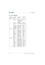
2. Voltage

Exit
1. U>>

off; 100…150 %

119 %

113 %

off

2. t

(OFF)

40 ms…60 min

500 ms

500 ms

--

3. U >

off; 100…150 %

114 %

110 %

110 %

4. t

 (OFF)

40 ms…60 min

1 s

1 s

1 s

5. U

(ON) MAX

off; 100…150 %

off

off

off

6. U

(ON) MIN

off; 1…100 %

off

off

off

7. U <

off; 1…100 %

80 %

80 %

80 %

8. t

(OFF)

40 ms…60 min

2.50 s

2.50 s

2.50 s

9. U<<

off; 1…100 %

off

off

off

10. t

(OFF)

40 ms…60 min

––

––

––

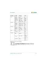
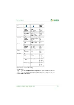
3. Frequency

Exit
1. f>>

off; 50.00…65.00 Hz

off

off

off

2. t

(OFF)

40 ms…60 min

––

––

––

3. f>

off; 50.00…65.00 Hz

52.00 Hz

52.00 Hz

52.00 Hz

4. t

 (OFF)

40 ms…60 min

500 ms

500 ms

500 ms

5. f 

(ON) MAX

off; 50.00…65.00 Hz

off

off

off

6. f 

(ON) MIN

off; 45.00…60.00 Hz

off

off

off

7. f<

off; 45.00…60.00 Hz

47.50 Hz

47.50 Hz

47.50 Hz

8. t

(OFF)

40 ms…60 min

20 s

20 s

20 s

9. f<<

off; 45.00…60.00 Hz

47.00 Hz

47.00 Hz

47.00 Hz

10. t

(OFF)

40 ms…60 min

500 ms

500 ms

500 ms

Summary of Contents for B93010045

Page 1: ...NA Network and system protection NS protection for monitoring the power feed in of power generation systems Software version D398 V1 2x Display software version D403 V2 2 VMD460 NA_D00001_05_M_XXEN 0...

Page 2: ...er Str 65 35305 Gruenberg Germany Tel 49 6401 807 0 Fax 49 6401 807 259 E Mail info bender de www bender de Bender GmbH Co KG All rights reserved Reprinting only with permission of the publisher Subje...

Page 3: ...nitoring of the phase voltage and line to line voltage 13 3 2 Disconnection 14 3 3 Re connection and special reconnections 14 3 3 1 Re connection and monitoring of the conditions 14 3 3 2 Exceptions o...

Page 4: ...asic program 4105_2 26 4 8 2 VDE AR N 4105 2018 basic program 4105_2 with several generating units 28 4 8 3 VDE AR N 4110 2018 11 basic program 4110 30 4 8 4 EREC G99 G98 C10 11 DIN V VDE V 0126 1 1 b...

Page 5: ...2 12 V2 2013 12 2014 09 V1 2014 12 2016 07 V1 2017 07 61 6 7 C10 11 2006 06 64 6 8 G98 1 4 2019 66 6 9 G59 3 2013 G83 2 2012 68 6 10 G99 1 4 2019 70 6 11 G59 2 2010 1 2011 72 7 Maintenance troubleshoo...

Page 6: ...Inhaltsverzeichnis 6 VMD460 NA_D00001_05_M_XXEN 01 2020...

Page 7: ...401 807 259 Germany 0700BenderHelp telephone and fax E mail support bender service de This manual is intended for qualified personnel working in electrical en gineering and electronics This signal wor...

Page 8: ...air Service Londorfer Stra e 65 35305 Gr nberg Field service On site service for all Bender products Commissioning parameter setting maintenance troubleshooting Analysis of the electrical installation...

Page 9: ...contact Bender immediately The devices must only be stored in areas where it is protected from dust humidity and spray or dripping water and in which the specified storage temperatures can be as sured...

Page 10: ...Germany these pol icies are implemented through the Electrical and Electronic Equipment Act ElektroG According to this the following applies Electric and electronic equipment are not to be included i...

Page 11: ...g to install connect and commission the device After successful commissioning keep the man ual within easy reach for future reference Only qualified personnel are permitted to carry out the work neces...

Page 12: ...tection equipment for the generating unit or as higher level decoupling protection the latter however only if the QU protection function directional reactive power und ervoltage protection may be disp...

Page 13: ...d monitoring functions are parameterised in detail Further details regarding calculation methods and device behaviour Whether the re connection takes place automatically or after manual acknowledge me...

Page 14: ...automatic re connection In the event of a detected fault in one of the tripping circuits interface switch fault the connection is controlled via the parameter Menu Settings Dig in Fault mem ory Fault...

Page 15: ...o off reconnec tion takes place after the delay time for connection t ON NORMAL has elapsed 3 4 Protective and monitoring functions 3 4 1 Voltage protection functions U U U and U The following voltage...

Page 16: ...s equal to the instantaneous value 3 4 2 Frequency protection functions f f f and f The following frequency protection functions are implemented in the VMD460 NA Frequency increase protection f f Freq...

Page 17: ...alue exceeds the response value for the duration of the corresponding response delay t OFF the protective func tion is tripped If the df dt measured value falls below the response value by the hystere...

Page 18: ...ift disconnection 3 4 4 Unbalance detection Menu 3 Settings 5 Unbalance 1 Function 2 Response value 3 Hysteresis 4 t OFF On one hand the unbalance is determined separately on the basis of the phase vo...

Page 19: ...ged and reset via the RESET button 3 4 6 Remote trip remote disconnection via ripple control receiver Menu 3 Settings 1 General 8 Remote trip A remote trip signal can be connected to the RTG1 and RTG...

Page 20: ...o password is set all parameters and device settings can be freely changed and configured It is possible to navigate through the menu even if the password protection is enabled The following parameter...

Page 21: ...n be sealed to prevent or detect unauthorised access 3 5 3 Reset device to factory settings Menu 4 System 12 Factory settings Via this menu the device can be reset to the factory settings 3 5 4 Histor...

Page 22: ...Functional description 22 VMD460 NA_D00001_05_M_XXEN 01 2020...

Page 23: ...contact are indicated on the delivery document When storing the devices in an environment where the temperature is wintry and cold Leave the devices to stand for 3 to 4 hours at room temperature befo...

Page 24: ...lyvoltageasspecified in the technical data The length of the connecting cable of the device connections DG1 2 D1 D2 DG3 4 D3 D4 RTG and RT1 is to be limited to 3 m In order to ensure the proper functi...

Page 25: ...drawing for screw mounting 4 6 DIN rail mounting Snap the rear mounting clip of the device into place in such a way that a safe and tight fit is ensured 4 7 Screw mounting 1 Use a tool to position th...

Page 26: ...iring diagram VMD460 NA basic program 4105_2 The following wiring diagrams are recommendations by Bender Oth er wiring options are possible in the context of the applicable stand ard 11 12 14 K1 DG1 2...

Page 27: ...signal contact K1 feedbacksignalcontacts optionally NC NO off 5 RTG RT1 RTG GND RT1 remote trip input optionally NC NO off 6 A B Service interface 7 Ron off Activate or deactivate the terminating resi...

Page 28: ...e PV inverters are shown as ex amples Fig 4 4 Wiring diagram VMD460 NA basic program 4105_2 with several generating units D2 DG1 2 D1 21 24 22 K2 L1 L2 L3 N 11 12 14 K1 N N L L USV L1 L2 L3 N 6 A 6 A...

Page 29: ...contacts optionally NC NO off 5 RTG RT1 RTG GND RT1 remote trip input optionally NC NO off 6 A B Service interface 7 Ron off Activate or deactivate the terminating resistor of the service interface 12...

Page 30: ...e after approval by the network control centre VDE AR N 4110 2018 11 chapter 10 4 2 par 1 In order to meet this requirement with the VDM460 NA the use of the remote trip func tion remote disconnection...

Page 31: ...emains in the alarm state until it is released again by the ripple control receiver Wiring diagram legend Explanation NC in non operating state closed NO in non operating state open off switched off N...

Page 32: ...99 C10 11 0126 Fig 4 5 Wiring diagram VMD460 NA basic programs G98 G99 C10 11 0126 L1 L2 L3 N 6 A 6 A 6 A US 6 A 6 A A1 A2 21 24 22 K2 11 12 14 K1 D2 DG1 2 D1 L1 L2 L3 N A B RTG RT1 D4 D3 DG3 4 VMD460...

Page 33: ...nections 4 DG1 2 D1 D2 Interface switch with contact monitoring D1 Feedback signal contact K1 D2 Feedback signal contact K2 feedbacksignalcontacts optionally NC NO off 5 RTG RT1 RTG GND RT1 remote tri...

Page 34: ...5 CEI 0 21 Fig 4 6 Wiring diagram VMD460 NA CEI 0 21 A1 L1 L2 L3 N A2 L1 L2 L3 D2 D1 DG1 2 11 21 US 24 12 22 VMD460 V LINETRAXX A B RTG RT1 D4 D3 DG3 4 11 12 14 21 22 24 L3 L2 L1 D2 D1 DG1 2 D4 N D3 R...

Page 35: ...on 3 DG1 2 D1 D2 Contact monitoring interface switch DG1 2 GND D1 Feedback signal contact K1 D2 Feedback signal contact K2 backup feedbacksignal contactoptionallyNC NO off 4 K1 K2 Relay connections 5...

Page 36: ...1 D4 RT1 Fig 4 7 Block diagram simplified representation In the event of a fault in interface switch 1 K1 the contact monitoring causes the backup relay K2 to switch low 4 V DC high 6 V DC Umax 30 V D...

Page 37: ...Wiring diagram VMD460 NA basic programs 4105_1 BDEW G59 3 G83 2 L1 L2 L3 N 6 A 6 A 6 A US 6 A 6 A A1 A2 21 24 22 K2 11 12 14 K1 D2 DG1 2 D1 L1 L2 L3 N A B RTG RT1 D4 D3 DG3 4 VMD460 LINETRAXX V RTG R...

Page 38: ...nections 4 DG1 2 D1 D2 Interface switch with contact monitoring D1 Feedback signal contact K1 D2 Feedback signal contact K2 feedbacksignalcontacts optionally NC NO off 5 RTG RT1 RTG GND RT1 remote tri...

Page 39: ...ce switches Successful activation must be visualised by the interface switch Contact monitoring of the interface switches optional depending on the standard Observe the information on recurrent tests...

Page 40: ...ights Reconnection conditions met t ON elapses 3 Backlit LC display 4 INFO ESC Standard display Standard display and device information Menu display Exit the parameter setting menu withoutsaving gotot...

Page 41: ...Fig 5 2 Info display For detailed information refer to Refer to INFO button on page 43 5 2 3 Alarm display Type and source of alarms are indicated on the alarm display in clear text format Fig 5 3 Ala...

Page 42: ...e of display standard display alarm display menu display info display the mean ing of the buttons is different The picture below illustrates which button is to be pressed for accessing the individual...

Page 43: ...m and menu display Refer to Toggling between the displays alarm condition or no alarm condition on page 42 The individual entries in the menu display can be accessed using the arrow buttons The menu d...

Page 44: ...icated alternately on the display every four seconds Measuring channel 16 Indicates the total time passed during the self test from simulat ing 0 V on L1 to disconnecting interface switch 1 Refer to M...

Page 45: ...Line 2 Start of the event Date time Line 3 Acknowledgement of the event Date time Line 4 End of the event Date time Possibilities 1 If you are searching for an event that occurred at a specific time s...

Page 46: ...his should be necessary The values can be changed in the third level of the menu column twice using There are two different ways to exit the setting menu Save and exit Exit without saving ESC The menu...

Page 47: ...ing between hour and minute with Summer time auto off 4 Password Exit Password Toggling between positions with State off on 5 Interface Exit Address 1 90 1 Master 2 90 Slave 6 Alarm addresses Exit Add...

Page 48: ...Scroll through the individual lines using the arrow buttons 1 Device name 2 Current date and time 3 BMS bus address 4 Software version measurement technology 5 Software date measurement tech nology 6...

Page 49: ...ener ating plant to the busbar of a substation 3 MV network higher level generating plant Protection of a generating plant at the network connection point when connected to the medium voltage network...

Page 50: ...eral profiles Selecting a profile MENU button 3 Settings 1 General 2 Profile The settings for the different profiles are made according to the loading of a standard The following tables give an overvi...

Page 51: ...U off 100 150 115 125 125 2 t OFF 40 ms 60 min 100 ms 100 ms 100 ms 3 U off 100 150 110 110 110 4 t OFF 40 ms 60 min 100 ms 100 ms 100 ms 5 U ON MAX off 100 150 off off off 6 U ON MIN off 1 100 85 85...

Page 52: ...ON off 40 ms 60 min off off off 5 Vect shift Exit 1 Function off L1 L2 L3 single all off off off 2 Resp value 1 0 25 0 8 0 8 0 8 0 3 t START UP off 40 ms 60 min 2 00 s 2 00 s 2 00 s 4 t ON off 40 ms...

Page 53: ...s 7 Remote trip NC NO off off 2 Voltage Exit 1 U off 100 150 115 2 t OFF 40 ms 60 min 100 ms 3 U off 100 150 110 4 t OFF 40 ms 60 min 100 ms 5 U ON MAX off 100 150 off 6 U ON MIN off 1 100 85 7 U off...

Page 54: ...0 0 20 0 4 Meas window 50 ms 1 s 200 ms 5 t OFF 40 ms 60 min 100 ms 6 t ON off 40 ms 60 min off 5 Vect shift Exit 1 Function off L1 L2 L3 single all off 2 Resp value 1 0 25 0 8 0 3 t START UP off 40 m...

Page 55: ...100 150 120 125 120 125 2 t OFF 40 ms 60 min 300 ms 300 ms 300 ms 300 ms 3 U off 100 150 110 off 110 off 4 t OFF 40 ms 60 min 180 s 180 s 5 U ON MAX off 100 150 off 110 off 110 6 U ON MIN off 1 100 90...

Page 56: ...5 Vect shift Exit 1 Function off L1 L2 L3 single all off off off off 2 Resp value 1 0 25 0 8 0 8 0 8 0 8 0 3 t START UP off 40 ms 60 min 2 00 s 2 00 s 2 00 s 2 00 s 4 t ON off 40 ms 60 min off off off...

Page 57: ...ote trip NC NO off off 2 Voltage Exit 1 U off 100 150 120 2 t OFF 40 ms 60 min 100 ms 3 U off 100 150 108 4 t OFF 40 ms 60 min 60 s 5 U ON MAX off 100 150 off 6 U ON MIN off 1 100 95 7 U off 1 100 80...

Page 58: ...20 0 4 Meas window 50 ms 1 s 200 ms 5 t OFF 40 ms 60 min 100 ms 6 t ON off 40 ms 60 min off 5 Vect shift Exit 1 Function off L1 L2 L3 single all off 2 Resp value 1 0 25 0 8 0 3 t START UP off 40 ms 6...

Page 59: ...ms 60 min 30 s 7 Remote trip NC NO off off 2 Voltage Exit 1 U off 100 150 115 2 t OFF 40 ms 60 min 100 ms 3 U off 100 150 110 4 t OFF 40 ms 60 min 100 ms 5 U ON MAX off 100 150 off 6 U ON MIN off 1 1...

Page 60: ...0 0 20 0 4 Meas window 50 ms 1 s 200 ms 5 t OFF 40 ms 60 min 100 ms 6 t ON off 40 ms 60 min off 5 Vect shift Exit 1 Function off L1 L2 L3 single all off 2 Resp value 1 0 25 0 8 0 3 t START UP off 40 m...

Page 61: ...AC 3 U L N U L L 50 260 V 87 450 V U L N 230 V 4 Mode off external1 local 2 off 5 t SHORT INT off 40 ms 60 min off 6 t ON SHORT INT 40 ms 60 min 7 t ON NORMAL 40 ms 60 min 70 ms 8 Remote trip NC NO of...

Page 62: ...13 Tex off 81 S2 40 ms 60 min 1 00 s 3 Frequency 14 Tex off 81 S2 40 ms 60 min 4 00 s 15 f off 45 00 60 00 Hz off 16 t OFF 40 ms 60 min 4 df dt Exit 1 Function off on off 2 Resp value 0 05 9 95 Hz s...

Page 63: ...lay is deenergised in normal operation and energised in the alarm state 2 Not used for CEI 0 21 2012 06 V1 2012 12 V2 2013 12 2014 09 V1 2014 12 8 Dig input D1 K1 D2 K2 backup D3 local control D4 exte...

Page 64: ...s 7 Remote trip NC NO off off 2 Voltage Exit 1 U off 100 150 115 2 t OFF 40 ms 60 min 100 ms 3 U off 100 150 110 4 t OFF 40 ms 60 min 100 ms 5 U ON MAX off 100 150 off 6 U ON MIN off 1 100 85 7 U off...

Page 65: ...4 Meas window 50 ms 1 s 200 ms 5 t OFF 40 ms 60 min 100 ms 6 t ON off 40 ms 60 min off 5 Vect shift Exit 1 Function off L1 L2 L3 single all off 2 Resp value 1 0 25 0 8 0 3 t START UP off 40 ms 60 min...

Page 66: ...emote trip NC NO off off 2 Voltage Exit 1 U off 100 150 119 2 t OFF 40 ms 60 min 500 ms 3 U off 100 150 114 4 t OFF 40 ms 60 min 1 00 s 5 U ON MAX off 100 150 off 6 U ON MIN off 1 100 off 7 U off 1 10...

Page 67: ...4 Meas window 50 ms 1 s 500 ms 5 t OFF 40 ms 60 min 100 ms 6 t ON off 40 ms 60 min off 5 Vect shift Exit 1 Function off L1 L2 L3 single all off 2 Resp value 1 0 25 0 12 0 3 t START UP off 40 ms 60 min...

Page 68: ...in 6 t ON NORMAL 40 ms 60 min 20 s 7 Remote trip NC NO off off 2 Voltage Exit 1 U off 100 150 119 2 t OFF 40 ms 60 min 500 ms 3 U off 100 150 114 4 t OFF 40 ms 60 min 1 00 s 5 U ON MAX off 100 150 off...

Page 69: ...0 20 0 4 Meas window 50 ms 1 s 200 ms 5 t OFF 40 ms 60 min 100 ms 6 t ON off 40 ms 60 min off 5 Vect shift Exit 1 Function off L1 L2 L3 single all off 2 Resp value 1 0 25 0 8 0 3 t START UP off 40 ms...

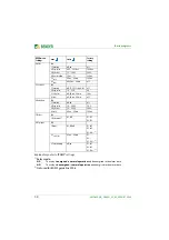
Page 70: ...1 U off 100 150 119 113 off 2 t OFF 40 ms 60 min 500 ms 500 ms 3 U off 100 150 114 110 110 4 t OFF 40 ms 60 min 1 s 1 s 1 s 5 U ON MAX off 100 150 off off off 6 U ON MIN off 1 100 off off off 7 U off...
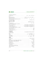
Page 71: ...100 ms 6 t ON off 40 ms 60 min off off off 5 Vect shift Exit 1 Function off L1 L2 L3 single all off off off 2 Resp value 1 0 25 0 12 0 12 0 12 0 3 t START UP off 40 ms 60 min 2 00 s 2 00 s 2 00 s 4 t...

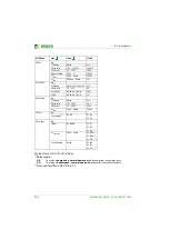
Page 72: ...e trip NC NO off off 2 Voltage Exit 1 U off 100 150 115 2 t OFF 40 ms 60 min 500 ms 3 U off 100 150 110 4 t OFF 40 ms 60 min 1 00 s 5 U ON MAX off 100 150 off 6 U ON MIN off 1 100 off 7 U off 1 100 87...

Page 73: ...0 4 Meas window 50 ms 1 s 200 ms 5 t OFF 40 ms 60 min 100 ms 6 t ON off 40 ms 60 min off 5 Vect shift Exit 1 Function off L1 L2 L3 single all off 2 Resp value 1 0 25 0 8 0 3 t START UP off 40 ms 60 m...

Page 74: ...of the interface switch Press the TEST button to trigger the interface switch Successful activation must be visualised by the interface switch The tripping circuit NS protection interface switch in th...

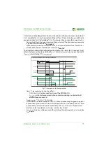
Page 75: ...l 17 t OFF DEVICE Fig 7 1 Comments on the timing diagram Times are measured during the self test t OFF DEVICE is the disconnection time of the VMD460 NA t OFF TOT will only be measured when contact mo...

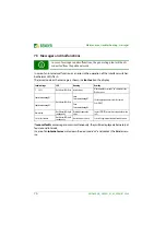
Page 76: ...rv ice In case of messages and malfunctions the generating plant will be dis connected from the public network Code message LED Meaning Remedy 1 20 23 Both alarm LEDs flash Internal error Write down t...

Page 77: ...eration device in operation all the measured values are within the specified limits yellow lights yellow lights green lights Alarm limit value violated yellow off yellow lights green lights Alarm stop...

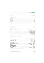
Page 78: ...ge Us AC DC 100 240 V DC 50 60 Hz Operating range Us AC DC 75 300 V DC 40 70 Hz Power consumption at AC 230 V 7 5 VA 3 5 W max 9 VA 3 5 W Bridging time at Us 230 V and dip to 0 V 600 ms Measuring circ...

Page 79: ...0 4 V Iin 5 mA open high 6 30 V D1 feedback signal contact K1 D2 feedback signal contact K2 D3 local control mode D4 external signal mode RT1 remote trip DG1 2 DG3 4 RTG GND Max length of the connect...

Page 80: ...erm storage IEC 60721 3 1 1K22 except condensation and formation of ice Classification of mechanical conditions acc to IEC 60721 Stationary use IEC 60721 3 3 3M4 Transport IEC 60721 3 2 2M4 Long term...

Page 81: ...atecnicadiriferimentoperlaconnessionediutentiattiviepassivialleretiBT delle imprese distributrici di energia elettrica CEI 0 21 2012 06 CEI 0 21 V1 2012 12 CEI 0 21 V2 2013 12 2016 07 V1 2017 07 C10 1...

Page 82: ...Technical data VMD460 NA 82 VMD460 NA_D00001_05_M_XXEN 01 2020...

Page 83: ...43 Info display 41 Installation and connection 23 Intended use 11 12 Interface switch 27 29 Inverter 27 29 L LEDs 40 M Maintenance 49 Measured values 44 MENU button 43 Menu display 42 Mounting clip f...

Page 84: ......

Page 85: ...ny Londorfer Str 65 35305 Gr nberg Germany Tel 49 6401 807 0 Fax 49 6401 807 259 E Mail info bender de www bender de Bender GmbH Co KG All rights reserved Reproduction only with permission of the publ...

Reviews: