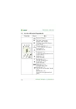
Function
17
CMD420_421-DM_D00224_01_M_XXEN/08.2016
3.2.4
Malfunction
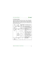
In the event of an internal malfunction, all three LEDs will flash. The error code
(E01…E32) will appear on the display. In such a case please contact the Ben-
der Service.
3.2.5
Fault memory
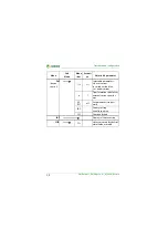
The fault memory can be activated, deactivated or set to continuous mode
(con). If the fault memory is set to "con“ mode, the alarm parameters remain
stored even on failure of the supply voltage.
3.2.6
Erasable history memory
The first alarm value to occur is written to this memory. The memory can be
erased via the HiS menu.
3.2.7
Start-up delay
t
After connection to the supply voltage, the LED alarm indication is delayed by
the preset time
t
(0…300 s). The analogue output value will be outputted wi-
thout a delay.
3.2.8
Analogue voltage or current output (option M)
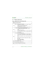
The device provides an analogue interface with galvanic isolation, but does
not provide an alarm relay. One of three output signals can be selected from
the "out" menu. A certain output is permanently assigned to the signal selec-
ted from the menu, only this output may be wired:
For wiring details refer to the wiring diagram on page 22.
Output signal
Terminal
Purpose of use
DC 0…400 μA
μA
Current output for Bender measuring instru-
ments of the 96.. series.
DC 0/4…20 mA
mA
Standardised current output with selectable
current ranges
DC 0…10 V
V
Standardised voltage signal


