System description
15
EDS309x_D00012_03_M_XXEN/11.2014
3.2.4
Coupling device AGE185
The coupling device AGE185 expands the nominal voltage range of the equipment for insulation
fault location EDS309…. It enables the equipment to be connected to system nominal voltages up
to AC 790 V or DC 960 V.
3.3 Operating principle for insulation fault location (
I
ΔL
)
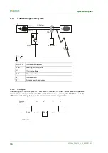
On the occurrence of the first insulation fault in IT systems a residual current flows that is essentially
defined by the system leakage capacitances. The basic concept of fault location is therefore to briefly
close the fault circuit using a defined resistance. With this principle a locating current is provided by
the system voltage and this locating current contains a signal that can be evaluated.
The locating current is generated periodically by the locating current injector PGH18… (part of the
EDS309…PG system).
The locating current can also be generated by an IRDH575 or a locating current injector PGH47….
The amplitude and duration of the locating current is limited. During this process the system con-
ductors are alternately
connected to earth via a defined resistance. The locating current produced as a result is dependent
on the magnitude of the insulation fault present and the system voltage.
For example the locating current on the EDS3090 is limited to maximum 25 mA; with the setting
I
max
= 10mA it is limited to 10 mA. During planning it is to be ensured that there are no system com-
ponents in which this locating current could cause a reaction involving damage in unfavourable cir-
cumstances.
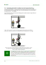
The locating current pulse flows from the locating current injector through the live conductors to the
insulation fault by the shortest route. From there it flows via the insulation fault and the earth cable
(PE cable) back to the locating current injector. This locating current pulse is detected by the meas-
uring clamps or measuring current transformers in the insulation fault path and is indicated by the
insulation fault locator EDS195P connected.
You must ensure that all live conductors are routed through the measuring
clamp.
Do not route any
protective earth conductors or screens on
screened cables
through the measuring clamp
! Commercial measuring
clamps are not suitable for the EDS309… and must not be used.
Only if these notes are observed will you obtain a correct measurement result.
You will find additional information in our technical information Techinfo08
"Transformer installation".
Summary of Contents for EDS3090
Page 6: ...Table of Contents 6 EDS309x_D00012_03_M_XXEN 11 2014...
Page 26: ...Considerations prior to use 26 EDS309x_D00012_03_M_XXEN 11 2014...
Page 62: ...Frequently Asked Questions 62 EDS309x_D00012_03_M_XXEN 11 2014...
Page 65: ......
Page 66: ......
Page 67: ......


