Operation
49
EDS309x_D00012_03_M_XXEN/11.2014
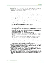
6.12.4 Usage of the EDS195P as a residual current meter
The EDS195P can be used as a residual current meter up to AC 10 A in TN and TT systems. Residual
current measurement is only possible in electrically live systems. The locating current
injector PGH18… is not required for this application.
1. Check whether the system voltage is within the permissible limits.
2. Switch on the EDS195P without a current transformer connected by pressing the
button.
The device undertakes a self-test and outputs the error message "No CT connected" because a
current transformer is not connected.
3. Now select the type of measuring clamp or measuring current transformer to be connected
using the
button. The device undertakes a further self-test and outputs the error message
"No CT connected" because a current transformer is not connected
4. Then connect the pre-selected measuring clamp or the pre-selected measuring current trans-
former to the EDS195P. The device undertakes a further self-test and is then in the EDS mode.
"I
Δ
L
" appears in the first line of the display.
5. Make the following settings:
– Change to the I
Δ
n (RCM mode) function using the related button
– Set residual current response value using the menu path "2. Settings /3. I
Δ
n ALM:"
6. On handling measuring clamps note:
– Do not bring measuring clamp into contact with system voltages above the nominal insula-
tion voltage. (See nameplate on the measuring clamp)
– During the measurement place the clamp around all system conductors,
but not PE
. Do not
place the clamp around screened conductors.
– Always keep contact surfaces on measuring clamp's iron core clean.
– Do not use measuring clamp in the immediate vicinity of devices that produce magnetic
fields such as transformers or chokes and also not near adjacent conductors carrying high
currents.
– Never disconnect measuring clamp from the EDS195P while it is placed around electrically
live conductors. Otherwise the measuring clamp may be irreparably damaged!
– Aim for the best possible symmetry of the conductors in the measuring clamp.
Otherwise the measuring clamp may go into saturation due to an excessively high load cur-
rent and cause an alarm I
Δ
n >10A.
–
Keep the measuring clamp still or let go of it
during the measurement!
– During the measurement do not apply any pressure to the clamp limb.
7. Start the measurement from the main distribution area of the system. Now measure along the
cable using the EDS195P until the insulation fault is found. During this process move into sub-
distribution systems using a star-shaped approach.
8. EDS195P indicates the residual current at each measuring point. If the residual current is
greater than the response value set, the "ALARM" LED illuminates and the measured value is
displayed. If the buzzer is activated, there is also an audible signal.
9. For long-term measurements at a point in the system, the fault memory is to be activated in
the menu 2.4 (Settings/Memory). In this way it is also possible to find intermittent residual cur-
rents provided they are above the response value set. The highest residual current measured is
saved.
Summary of Contents for EDS3090
Page 6: ...Table of Contents 6 EDS309x_D00012_03_M_XXEN 11 2014...
Page 26: ...Considerations prior to use 26 EDS309x_D00012_03_M_XXEN 11 2014...
Page 62: ...Frequently Asked Questions 62 EDS309x_D00012_03_M_XXEN 11 2014...
Page 65: ......
Page 66: ......
Page 67: ......

